Well Schematic
This subsection covers how to set up a new well schematic.
Defining Your Well Sections
There are different casing and string types for different functions and drilling conditions. Depending on the casing and string type that you add, different information will have to be defined.
- Add a new well schematic section
- Define the input
- Set the initial conditions
- List the strings in the section
- Set the kick tolerance
- Itemize the packers (for tubing only)
- Designate the design factors
NOTE!
There are many factors affecting casing selection. The initial selection is based on pore pressure and fracture pressure gradients for the well. This information is defined in Oliasoft's Formation Inputs module.
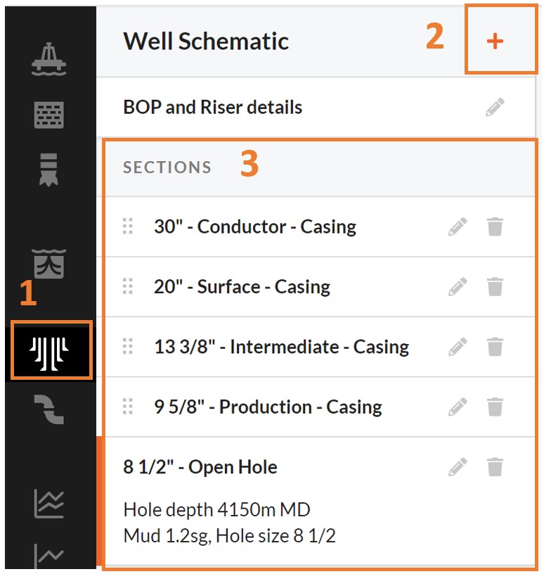
Add a New Well Schematic Section
Each new Section is stored in the Sections pane where it can be defined, edited or deleted. Once Well Schematic (1) is selected, new Casing Section can be added to the desired depth.(2). All your defined sections with increasing depth are listed and available in the Well Schematic pane (3).
Define the Input
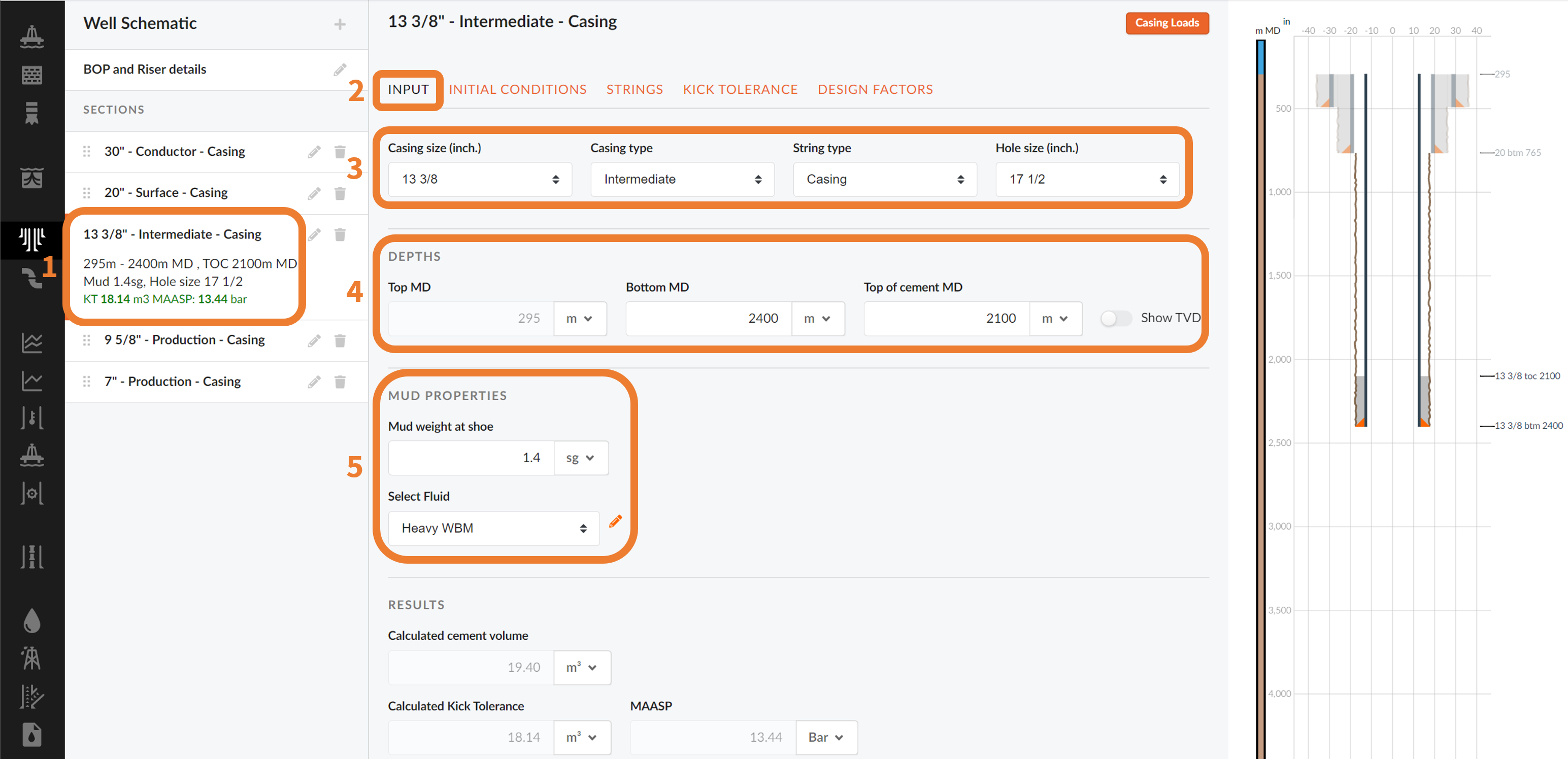
Once a new section is added or an existing one is highlighted (1), you can move to the Input tab (2) shown in the figure above.
The Input tab allows you to:
- Select the casing and string type and hole size (3)
- The top and bottom as well as the top of cement is set. The reference point is the rotary kelly bushing (drill floor). Thus, the depth notations are in MD RKB (4)
- Mud properties (5)
As a new input is defined, the section is added to the drawn well schematic 2D well section viewer in the right hand side of the interface.
NOTE!
Based on the geometry of the well, the cement volume is calculated and displayed.
Set the Initial Conditions
Once a new section is added or an existing one is highlighted (1), you can move to the Initial Conditions tab (2) shown in the figure below.
The Initial Conditions tab allows you to:
- Set Hole and Float Depths (3)
- Specify Fluid Properties (4)
- Select the Cement Type (5)
- Choose a Temperature Profile (6)
- String Conditions (7)
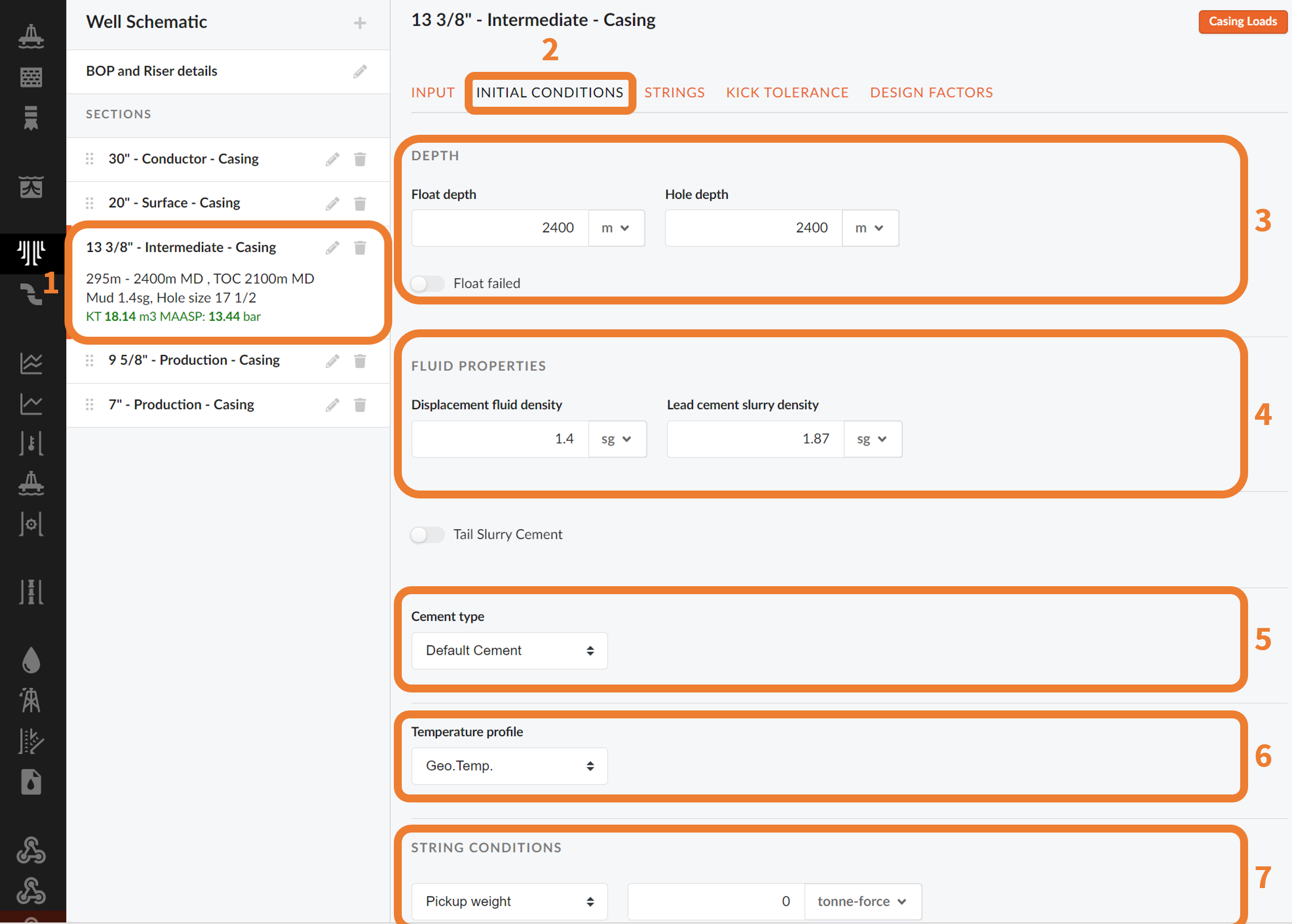
NOTE!
Cement types are defined in the Libraries.
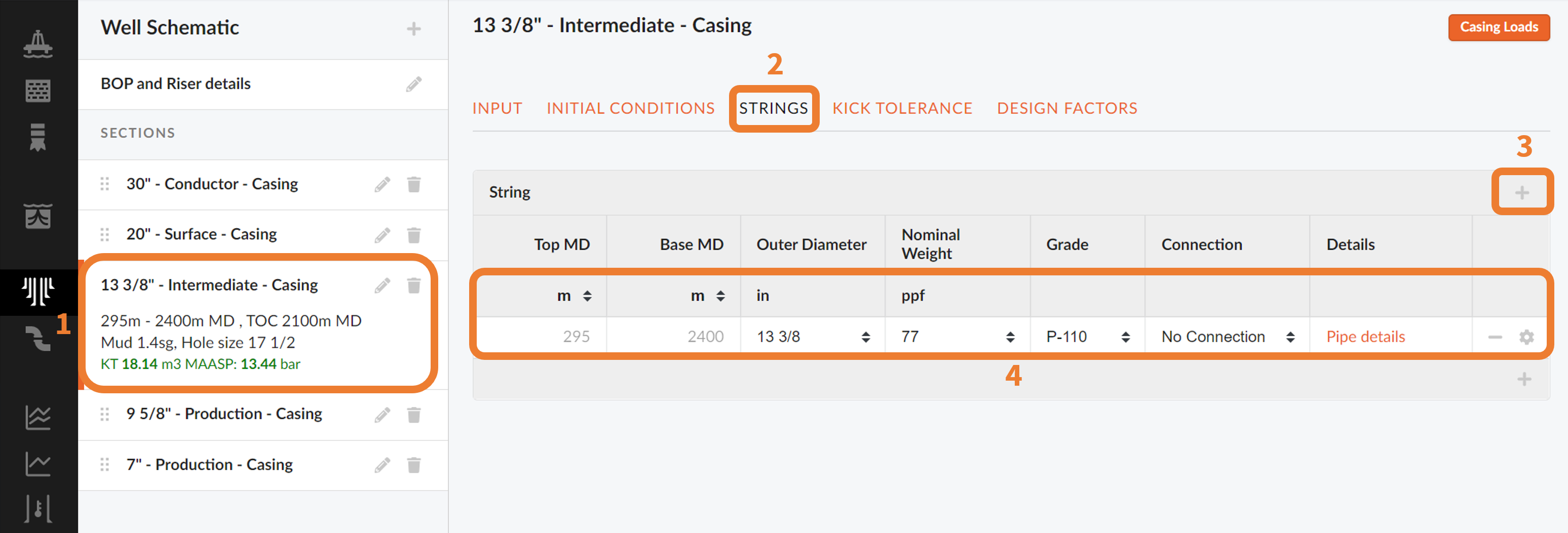
List the Strings in The Section
In this tab, the top and base of the casing strings are defined. Outer diameter, Nominal Weight and Grade are selected from the drop-down menus, available in each input field. Based on that information, the connection dropdown will only display the correct connections. Click the arrow to the left in the table to get more detailed information about the specific casing.
In cases of a tapered string, click the “+” icon at the bottom of the table to add a new casing string.
If the weight and grade you want to add does not already exist in the library, you can add them manually in Libraries.
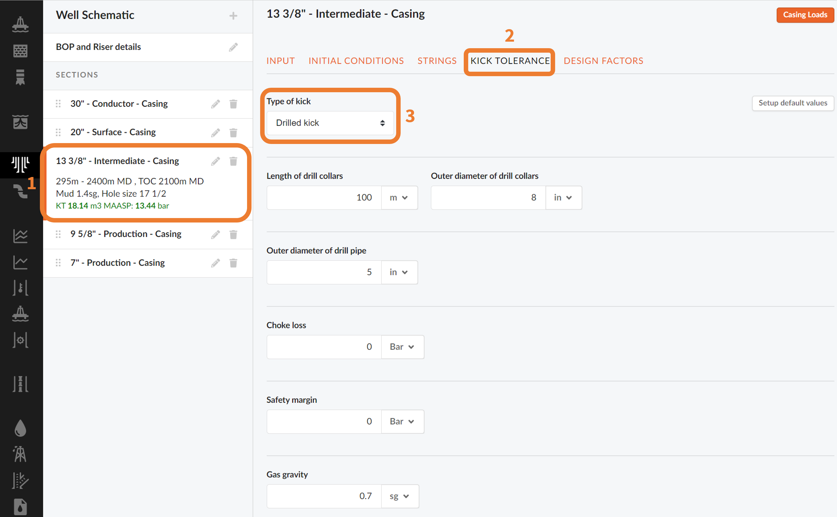
Set the Kick Tolerance
For any given Intermediate or Production casing or liner, or an open hole string type defined in your well schematic sections (1), you can set a kick tolerance (2). This will allow you to define the maximum gas volume influx in which the circulation can happen without exceeding the weakest formation.
The type of kick is selected from the list (3):
- Drilled Kick: pore pressure and mud weight are taken from the section to be calculated.
- Dynamic Kick: pore pressure at TD is set equal to the mud weight.
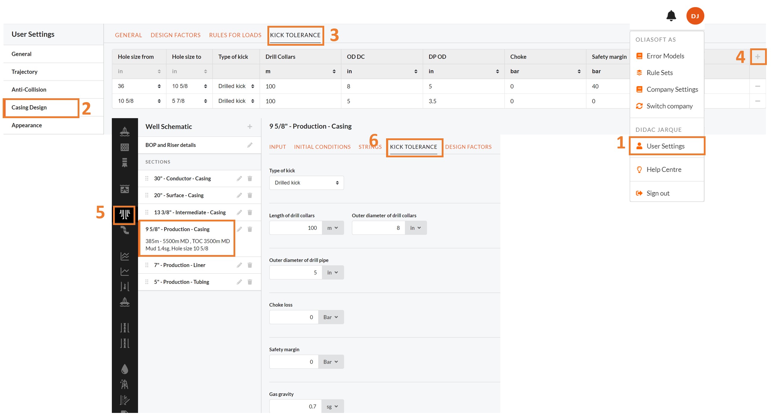
To set you own user defined kick tolerance you should:
- Go to User Settings
- Select Casing Design
- Pick Kick Tolerance
- Add a new Kick tolerance and define it. This will automatically apply the settings to all the sections with the same hole size you define in your different Projects.
- Go back to select a section in your Well Schematics.
- Select the Kick tolerance and check that the default values are the ones described for the newly defined settings.
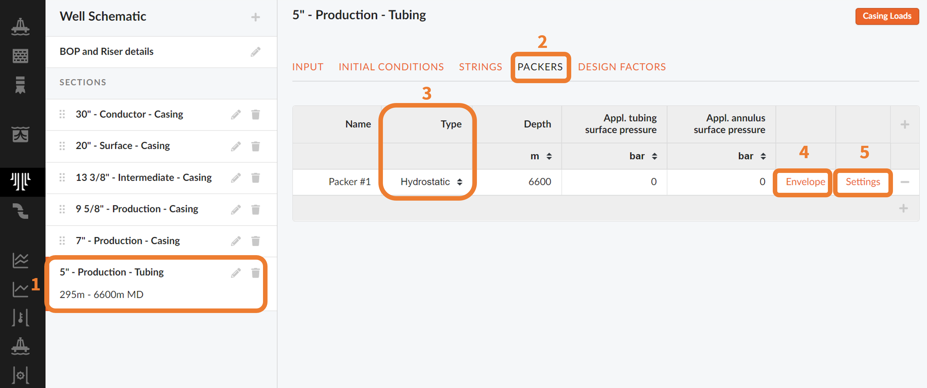
Packers
For any Tubing Sections (1), you will be able to specify the use of either Hydraulic or Mechanical (3) sealing packers at given depths. You can also specify the tubing to packer force and pressure in the packer envelope (4).
NOTE!
The Packer Envelope templates are stored in your Libraries. You can create User or Company Packer Envelope Libraries.
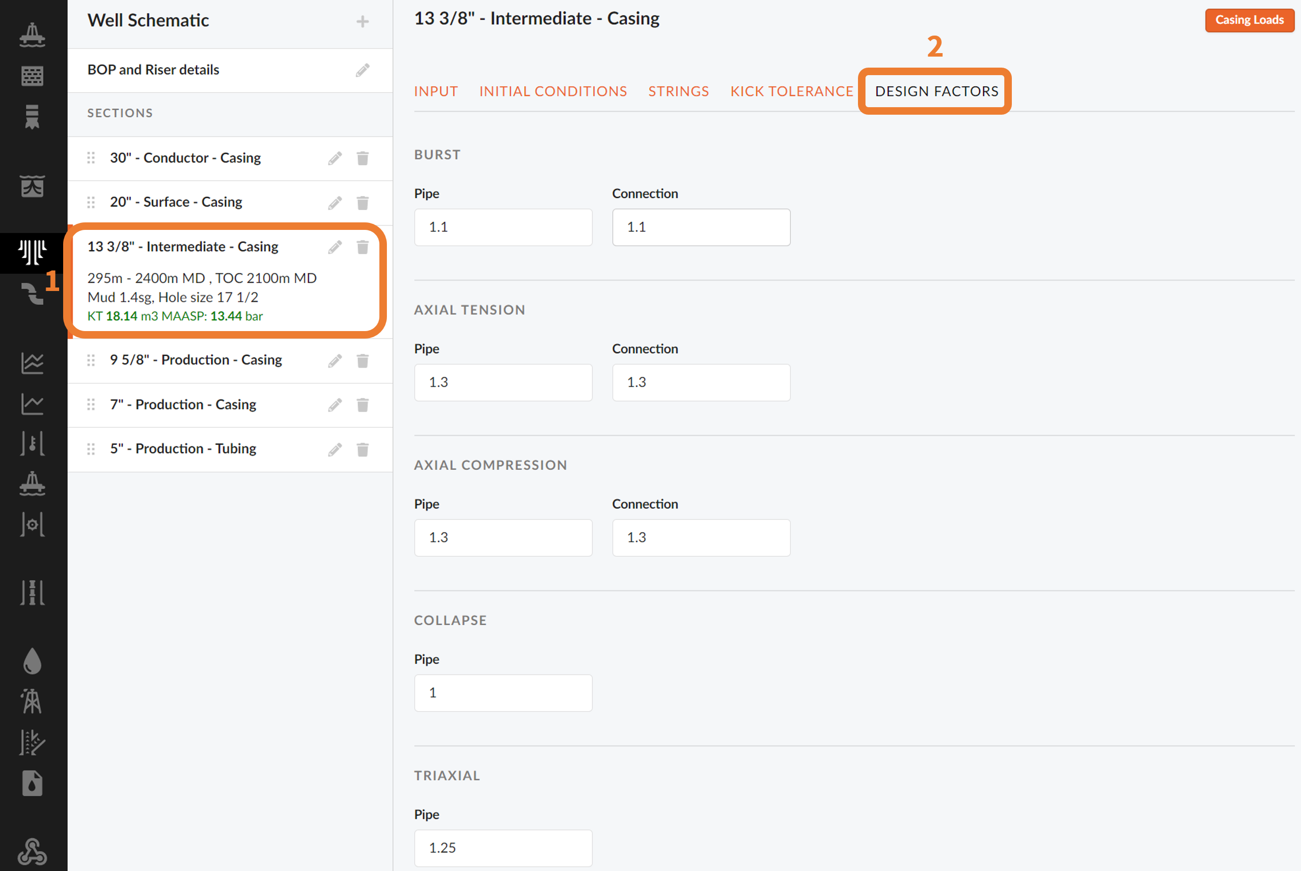
Design Factors
In this tab, the design factors (2), or safety factors, can be set individually for the different casing strings (1). This will allow us to design safe, reliable casing strings.
NOTE!
User defined Design Factors can be defined in your User Settings.
The well schematics will be generated automatically based on the defined casing sections and give a visual representation of your casing design.
Once you are done setting your Well Schematic, you are ready to define your Casing/Tubing Loads.