How to Create a Target
This subsection explains how targets are created and modified.
Well paths are built with respect to desired targets. A new target is added by clicking the "+" icon next to Targets.
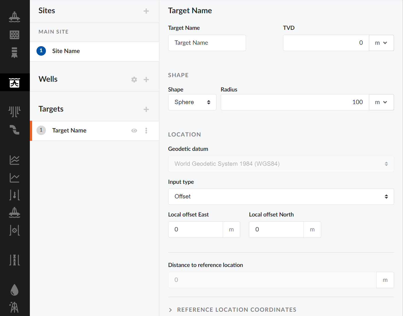
After creating a new target, a target menu pops up as shown abpve. A Target Name can be assigned to the target as well as defining the location of the target in True Vertical Depth (TVD).
The target shape can be defined by five different geometric relations:
| Shape Name | Explanation |
|---|---|
| Box | Cube defined by width, height, and depth |
| Cylinder | Cylinder defined by radius and height |
| Point | Point at target location |
| Rectangle | Rectangular plane defined by width and height |
| Spehere | Sphere defined by radius |
The location of the target is defined by two systems; geodetic datum and input type.
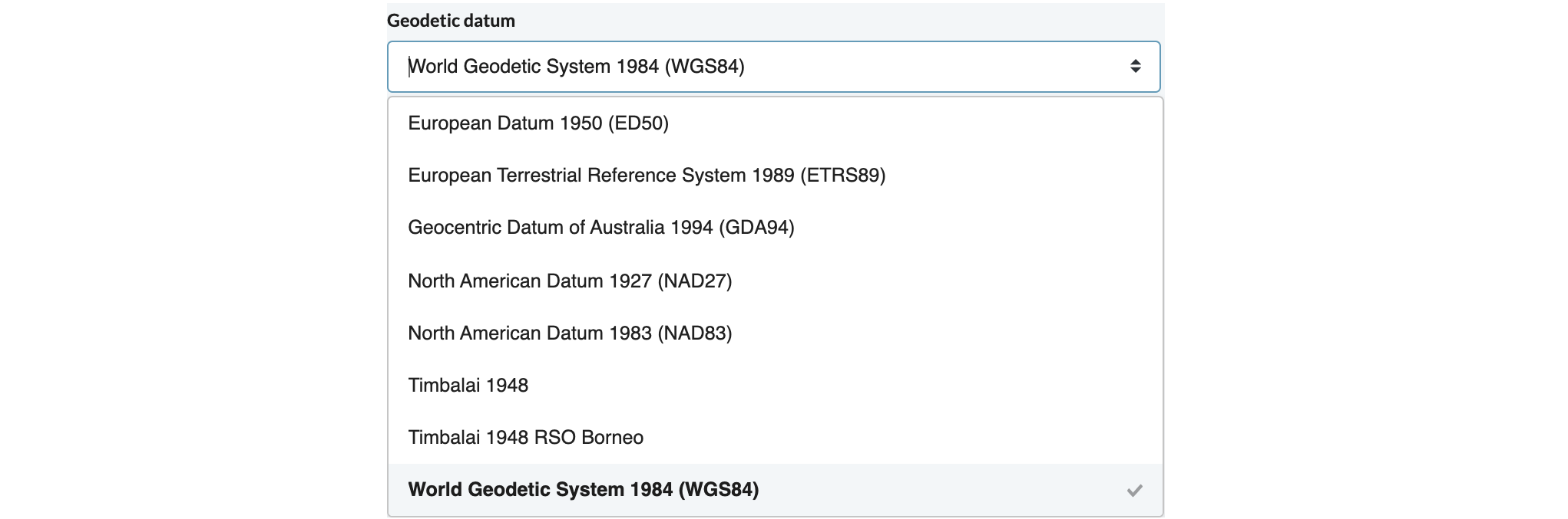
Geodetic Datum
The geodetic datum field shown below lets you choose the reference frame to be used when defining the target location on the curved surface of the earth. The following options are available in the Oliasoft Welldesign™ application.
Input Type
The input type field shown below lets you select the reference frame for defining the location of the target on a flat surface.

The following four options are available through Oliasoft Welldesign:
| Input Type | Explanation |
|---|---|
| Universal Transverse Mercator [UTM] | Coordinates defined by Easting and Northing, where Easting is the distance from the prime meridian and Northing is the distance from equator |
| Decimal Degrees [DD] | Coordinates given in Latitude and Longitude as decimal fractions of a degree |
| Degrees / Minutes / Seconds [DMS] | Coordinates given in Latitude and Longitude as [DMS] with reference to some geographic direction. Degrees are divided into 60 minutes of arc and minutes are divided into 60 seconds of arc. |
| Offset | Coordinates given by local offset to set site location. |
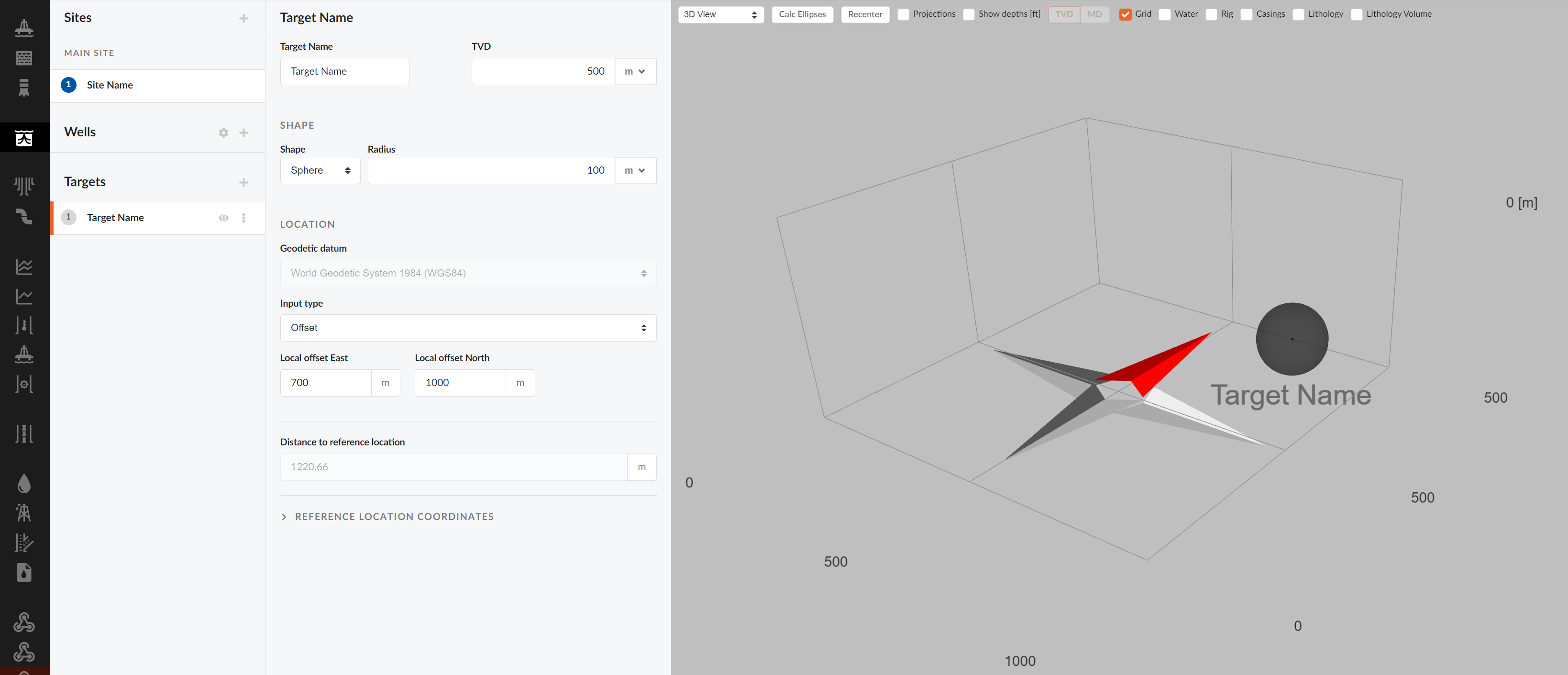
When shape and location is set, the new target can be inspected in the 3D View.