Common Input Data
In order to run any simulation, some common input data needs to be defined:
- Well Schematic Section
- Surface Equipment
- Simulations Options
- Drill String Section
- Drilling FLuid
- Tortuosity
- Riser Installed
- Simulation Depth
Choose a Well Schematic Section
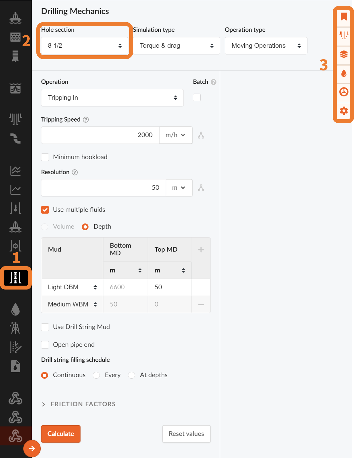
The “open hole” section to run simulation in is chosen in the upper tab (2) in the figure above. E.g. if you want to perform a T&D analysis when drilling or tripping in the 12 ¼ section you choose 12 ¼ tab. Your drill string will then go inside the 13 3/8 casing to the bottom of that string and continue all the way down to your defined TD of the 12 ¼ section. (From casing design). This is the basis for this calculation.
A slider (3) shown above indicates the TD of your selected section and is by default the depth used in the simulation. If you wish to change this depth you can move the slider to define the depth you wish to use as a basis for your calculation. This lets you e.g. conduct sensitivity analysis on setting depths of casing sections.
Define the Surface Equipment
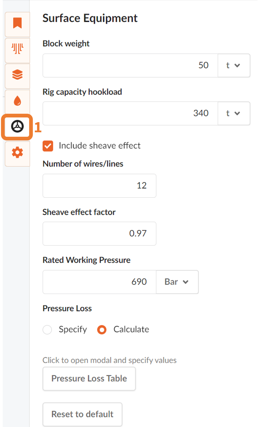
You can also define Surface equipment for Hydraulics and Surge & Swab equipment. Press the Surface Equipment button (1) in the figure below, located in the top right corner of the interface. Surface equipment will always start with default values. The edited boxes and parameters are automatically saved when exiting the right-hand menu.
Simulation Options
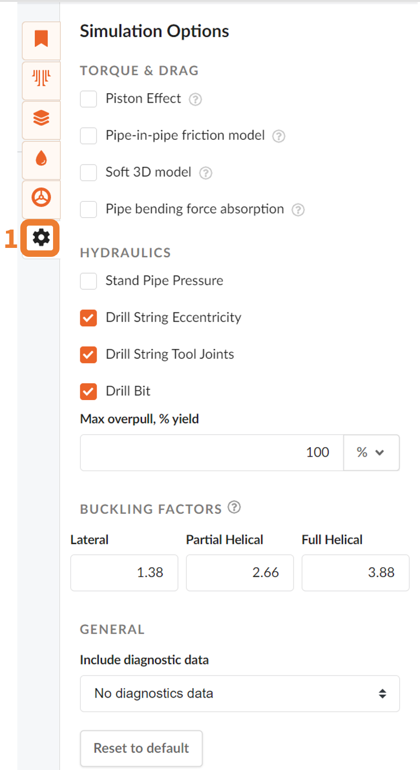
Simulation options (1) lets you define different parameters for your simulation. Select your desired parameters and return. Default values are used if the options are not altered.
Choose a Drill String Section
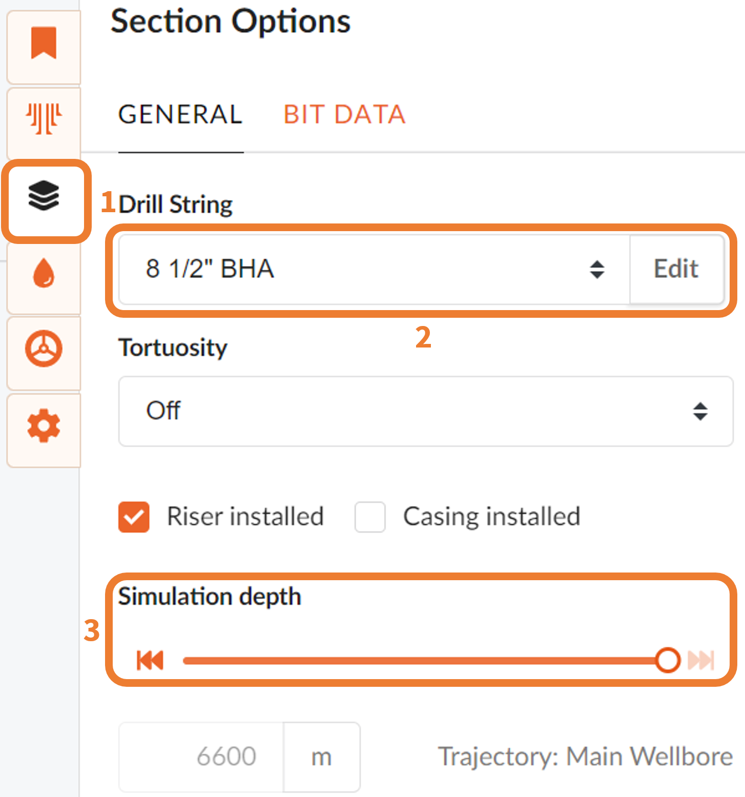
In order to perform an analysis you need to define a drill string. To choose a drill string press the empty box under Drill string header. Here you can choose a drill string from constructed in the string/BHA section of the application. To see how you can design a drill string/BHA follow this ***link*** or view video tutorial ***here***.
Edit lets you edit sections or parts of your drill string directly in the Drill String Analysis page. Edit drill string components or add new components by pressing + in the top left corner. To change the order of components drag and drop the different components.
Bit Data lets you define bit parameters. If not selected, default values will be used.
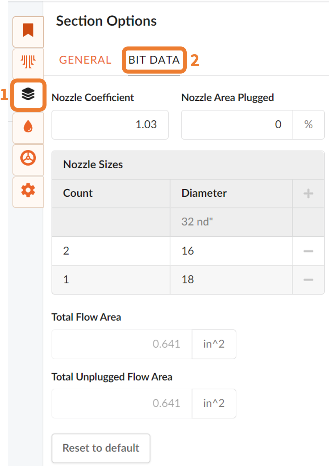
NOTE!
To enable Bit Data make sure you have selected "Drill Bit" in simulations options.
Choose or Create a Drilling Fluid
To select a drilling fluid click on the button labeled *Please Select* to open the Drilling Fluids modal. From the drop-down at the top of the modal you can select either a Custom or library drilling fluid.
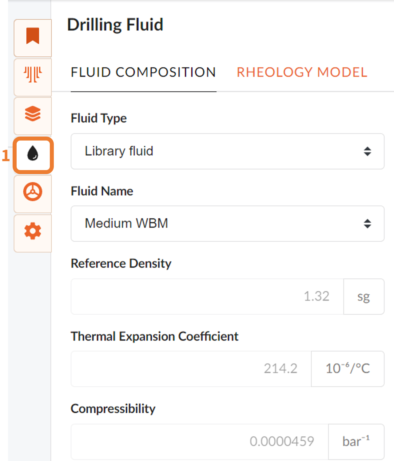
If you choose to define a custom drilling fluid you have to options for defining the rheology, either using single value inputs or compositional definition. The single value option requires you to add a density, thermal expansion coefficient and compressibility. The compositional option requires you to define the fluid composition in terms of water/brine, oil and solids. Based on the inputs a density will be calculated in addition to the pressure, density, thermal expansion coefficient and compressibility at temperatures between 0 and 100 degrees.
In the Rheology Model section of the modal you can select which rheology model to use in the calculations and you can also add a custom rheology to quickly override the rheology added in the library.
Tortuosity
You can select if you wish to add tortuosity effects to your well. Click on the Tortuosity button to apply tortuosity effects and enter data in the open fields. You can choose from; On, Off, On random or Angel Perturbation .
Riser Installed
This check box lets you select if riser is installed for current section, for offshore operations.
Specify Depth
Set the desired TD you wish to simulate to.