Casing and Tubing Loads
Load cases and corresponding design safety factors are the criteria used to judge the suitability of a design. Casing is subjected to different loads during landing, cementing, drilling, and production operations. The most important loads which it must withstand are tensile, burst and collapse loads.
New Casing Loads
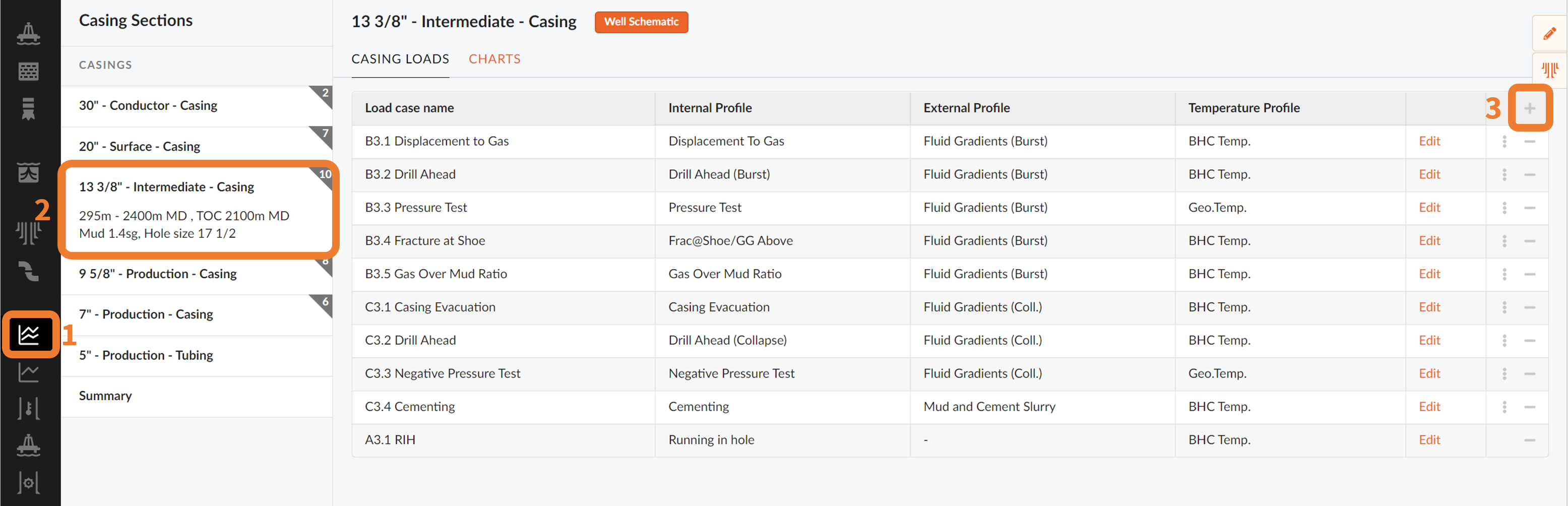
Once the Casing/Tubing Loads module has been selected (1), for any of your casing sections (2) specified under Well Schematics, you will be able to add new casing loads (3).
Define Casing Loads
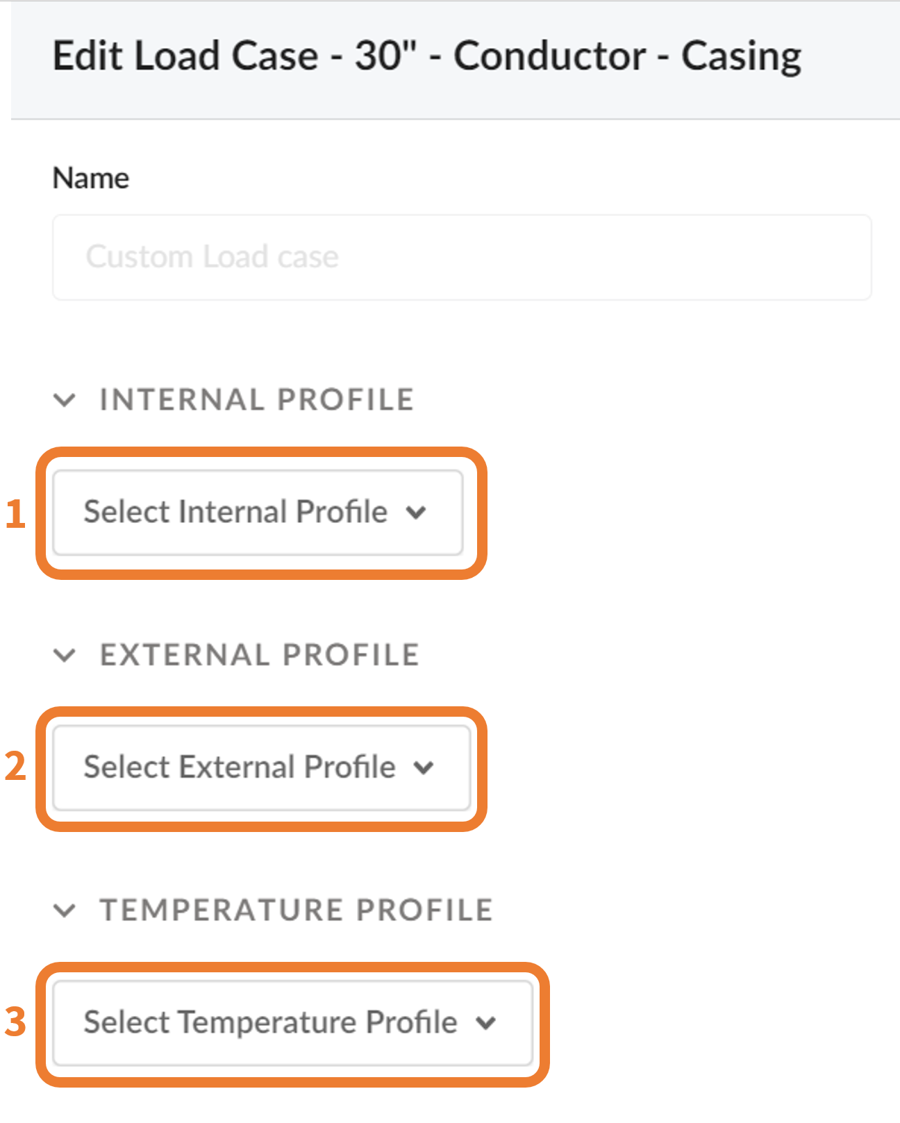
Once a new Case Load has been added, select the type of load case (1) from the dropdown menu under Internal Profile, and provide the necessary input parameters. Specify the external pressure profile (2) in the second drop down menu, and select the desired temperature profile (3) in the third drop down menu.
These three profiles constitute a scenario for any given casing or tubing section. Comparing this new set of conditions associated to a given scenario, it is possible to calculate the axial load, related safety factors and stress when compared to the initial conditions.
NOTE!
The notation Xx1.x2 is used for all load cases,where B, C and A represents burst (B), collapse (C) and axial load case (A) respectively, x1 is the casing section, number x2 is the number of load case for that specific casing section.
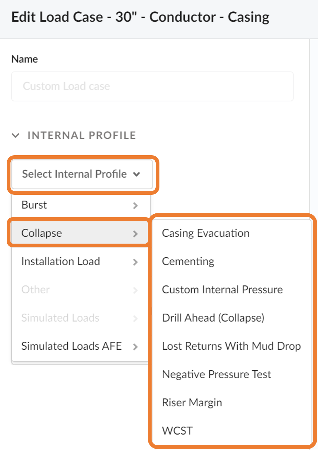
Internal Profile
The casing string must be designed to withstand the expected conditions in tension, burst and collapse. The below Loads are available to be added to the internal profile of your casing sections:
Burst
These are types of service loads that occur after the string has been installed, given a scenario. The whole casing string must be capable of withstanding the maximum anticipated formation internal pressure that the casing string could possibly be exposed to, without failing in burst. Here you can choose from several Burst internal loads.
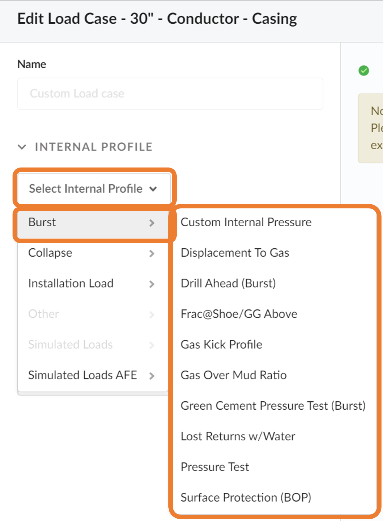
NOTE!
Custom Internal Pressure can be defined in the Custom Loads module.
Collapse
These are types of service loads that occur after the string has been installed, given a scenario. The design criteria will be based on the maximum hydrostatic pressure resulting from the mud weight that will be in the hole when the casing string is run.
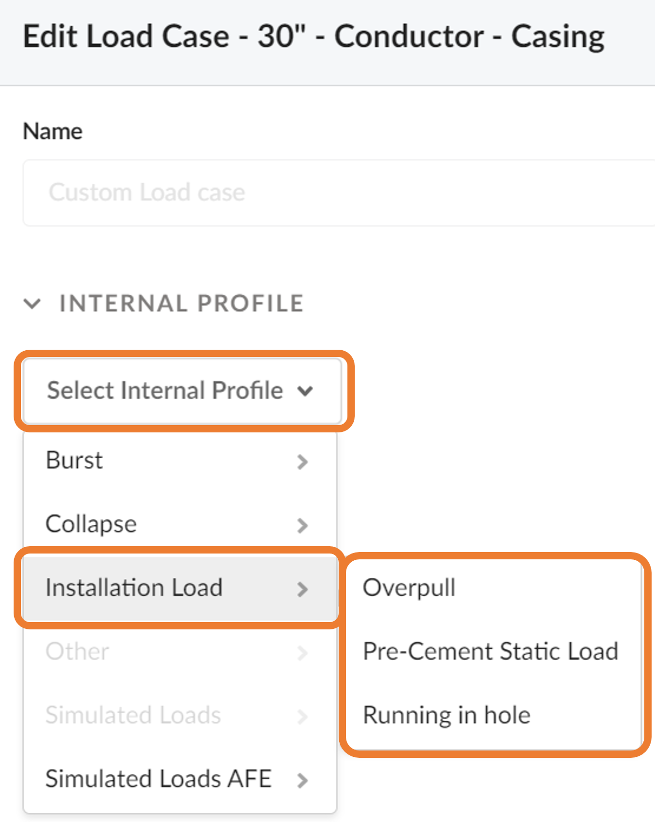
Installation Load
These loads occur due to installation of the string, defined in the String/BHA module. The design is based on the weight of the entire casing string.
Simulated Loads
Here choose to use any of the already simulated pressures calculated in the Temperature Simulation module.
Simulated Loads AFE
Here choose to use any of the already simulated pressures calculated in the Annular Fluid Expansion (AFE) module.
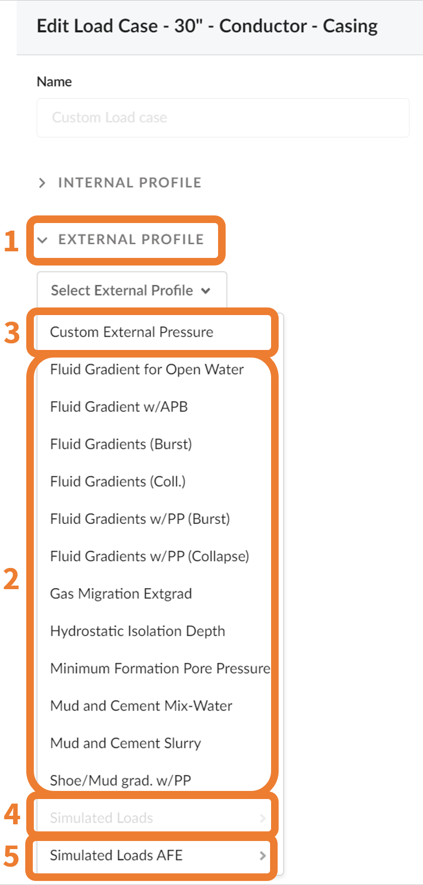
External Profile
External pressure profiles (1) have been added as predefined Loads (2) for any given casing sections. Custom pressure profiles per depth (3) can also be used. Also the simulated pressures from the Temperature Simulation (4) and the Annular Fluid Expansion results (5) can be used here.
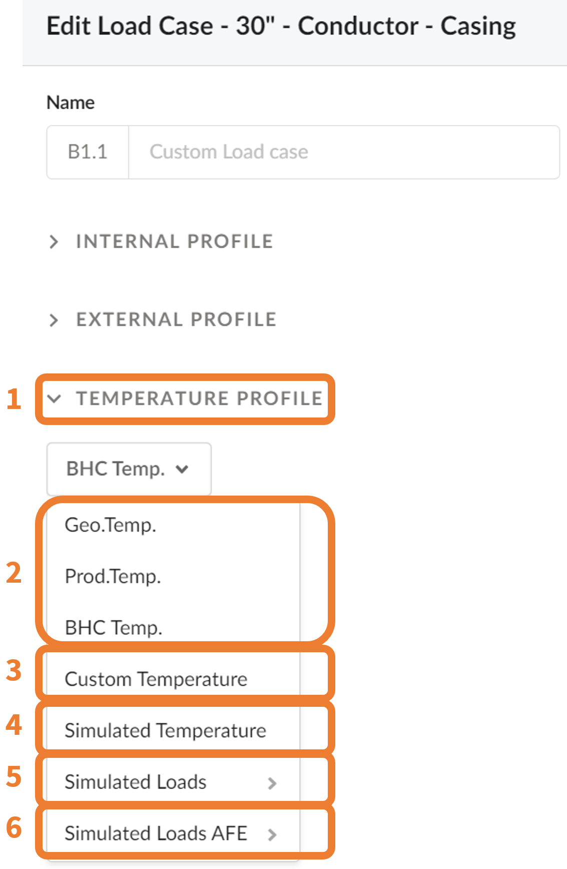
Temperature Profile
Choose from a range of temperature profiles (1), either related to the Formation Inputs (2), User defined (3) in the Custom Loads, , the simulated temperatures in the Temperature simulation module (4), or from the Simulated Loads (5) or the Annular Fluid Expansion module (6).
Visualizing Your Casing Loads
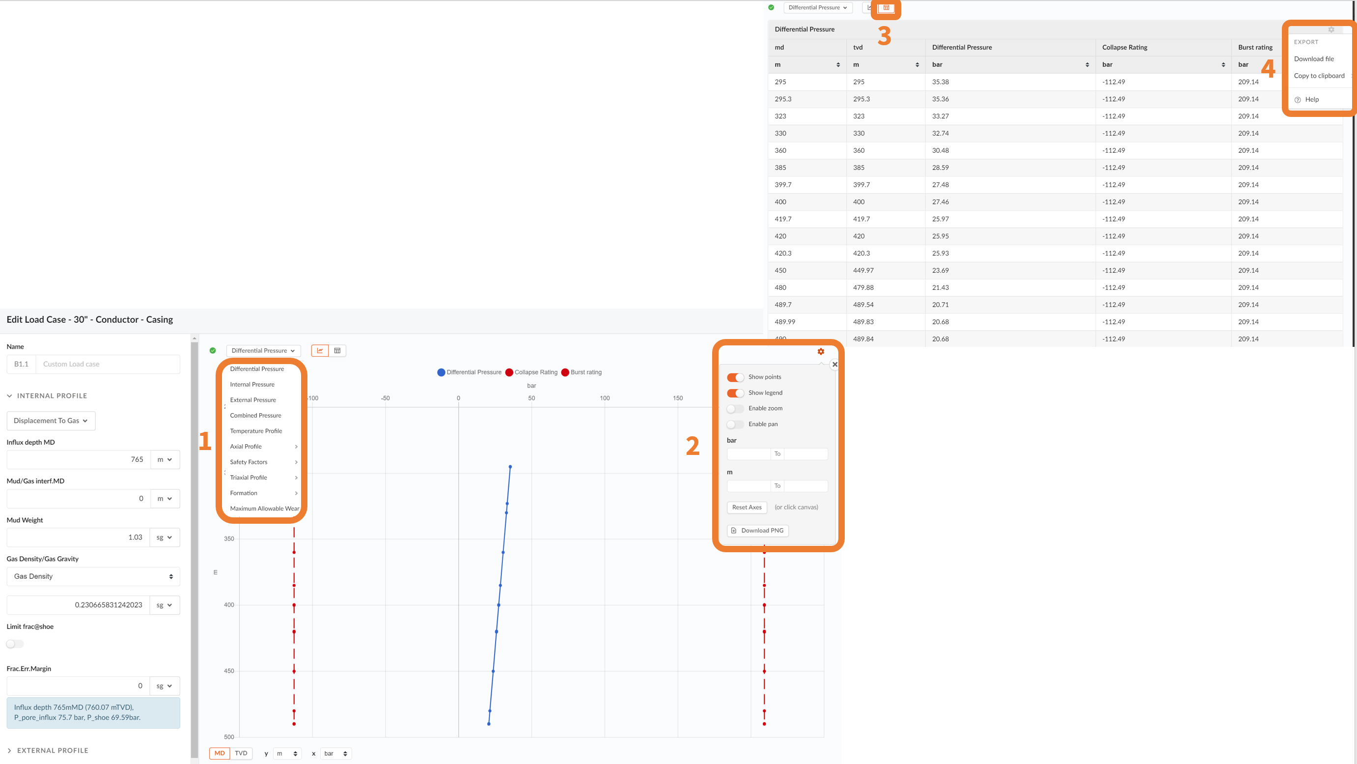
While you are defining your Load, different graphical visualizations can be displayed (1). You may change the Settings of the visualization (2).
The plot results can also be displayed in the form of a spreadsheet (3) and eventually, exported (4).