FAQ
If you're not finding the answer to your question on this website, this page will help you. If you're still unsure, don't hesitate to send your question to us directly.
General
1. Still quite a few teething problems – several bugs found. Some modules seem not to be fully developed yet.
The application is being validated by Equinor. The process is referred to as TRL and is soon coming to an end with the six modules being TRL4 approved. The TRL4 approval means that Equinor regards the modules to be ready for commercial use. Link to published verification documents: https://info.oliasoft.com/verification-reports
2. Setting up of permissions and restrictions not clear (not even sure if possible). Data locking not feasible.
We are currently releasing new functionality allowing the users to lock datasets. We will also implement access roles in a short time, where each user can be assigned a specific role which defines what the user has access to.
3. Easy to switch. Selection of units remains when re-opening.
In addition to the standard unit templates, NCS and API, it is possible to define custom unit templates in the User Settings.
4. The ability to make a custom unit set for the project.
Users can create custom unit templates which can be applied in specific datasets.
How to create custom unit templates:
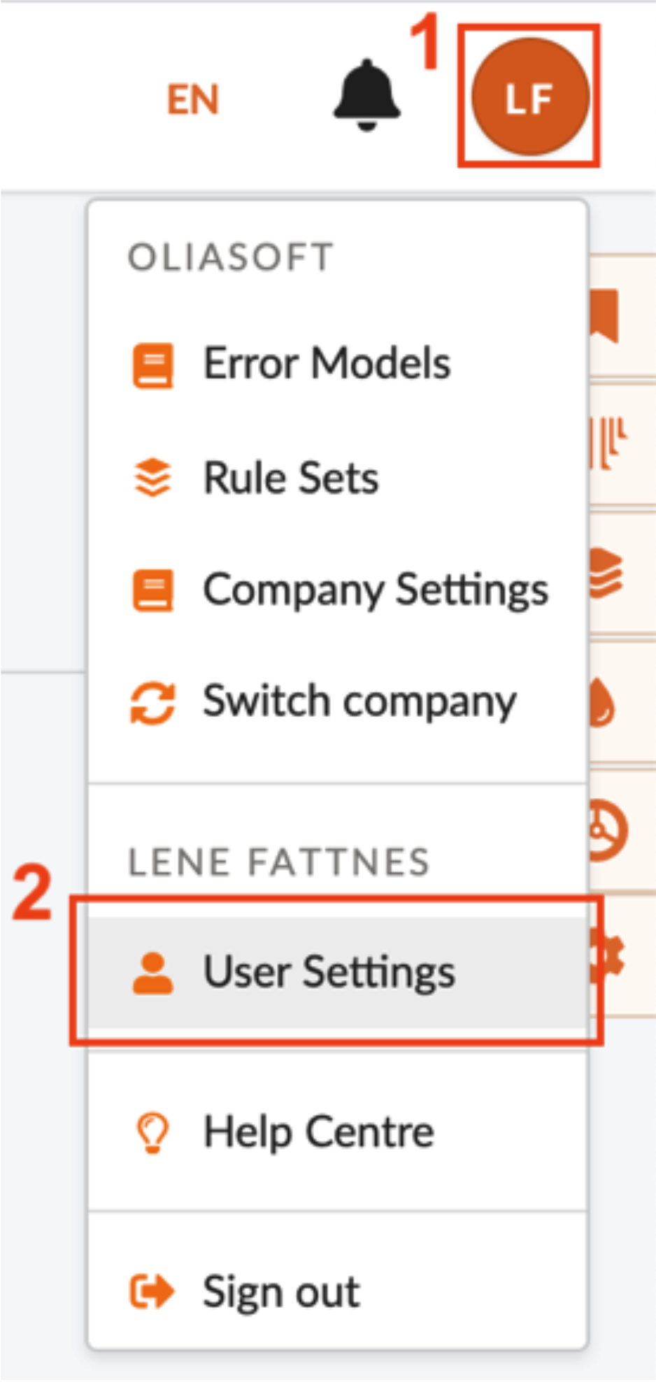
Click the button with your initials in the upper right corner and select the “User Settings” option
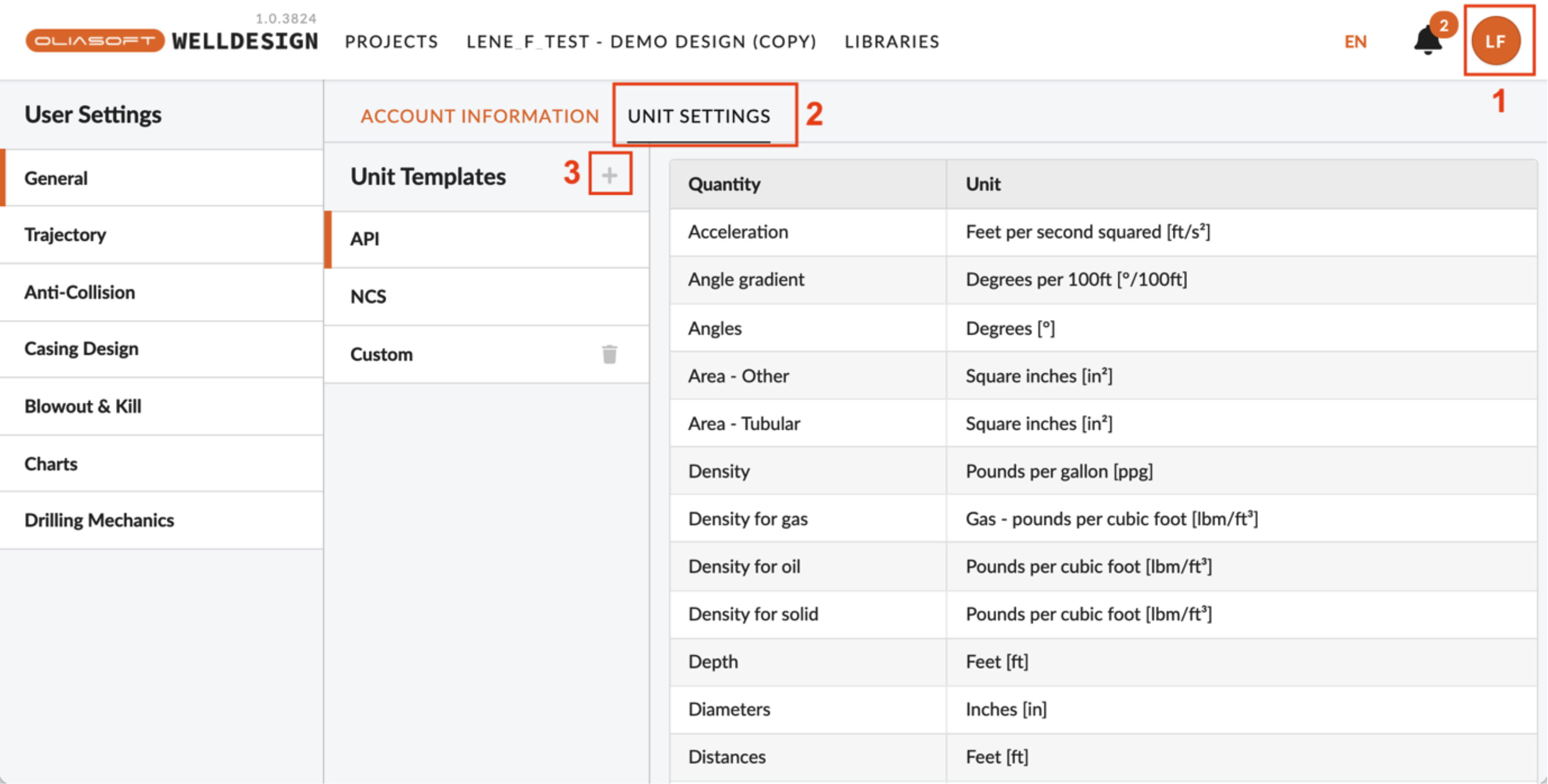
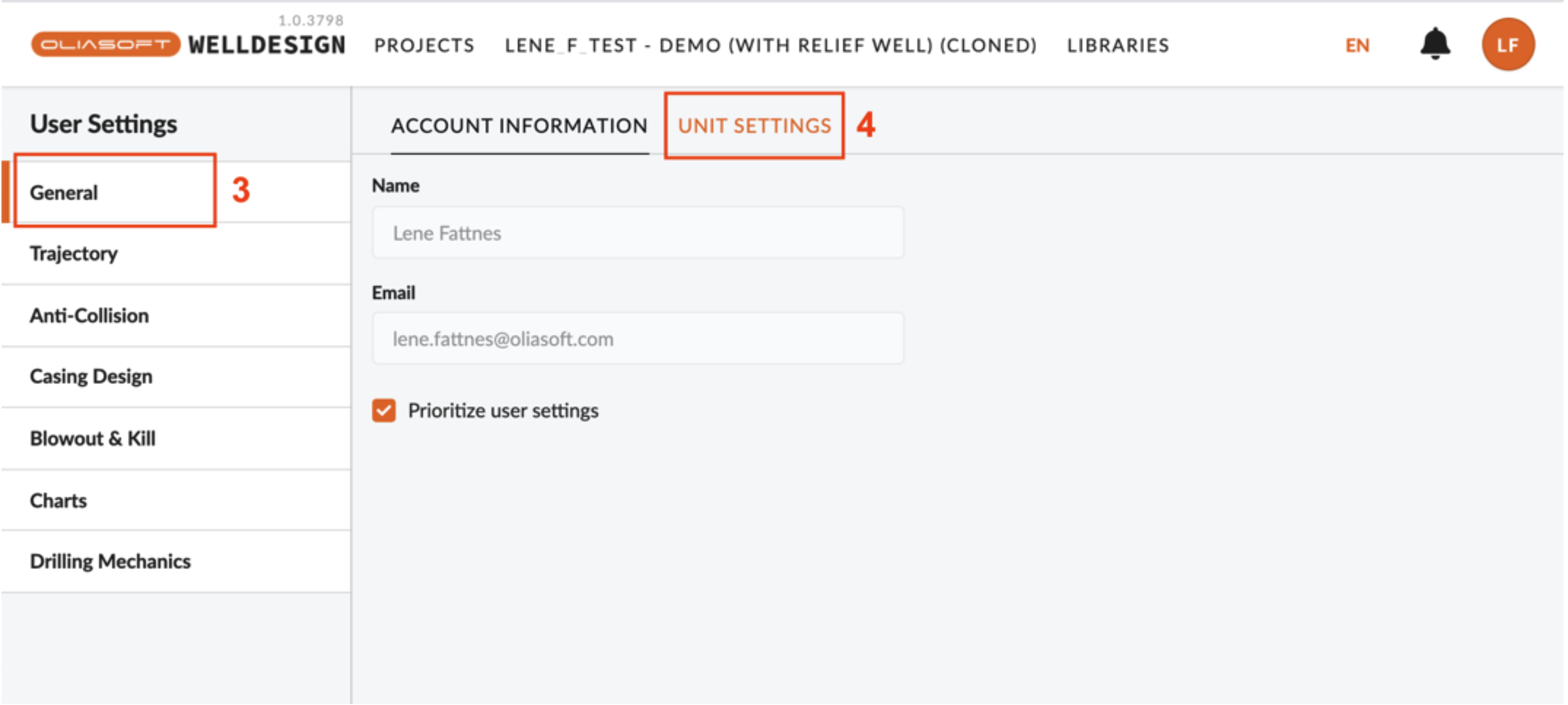
You will be taken to the following page where the “Unit Settings” tab is to be selected.
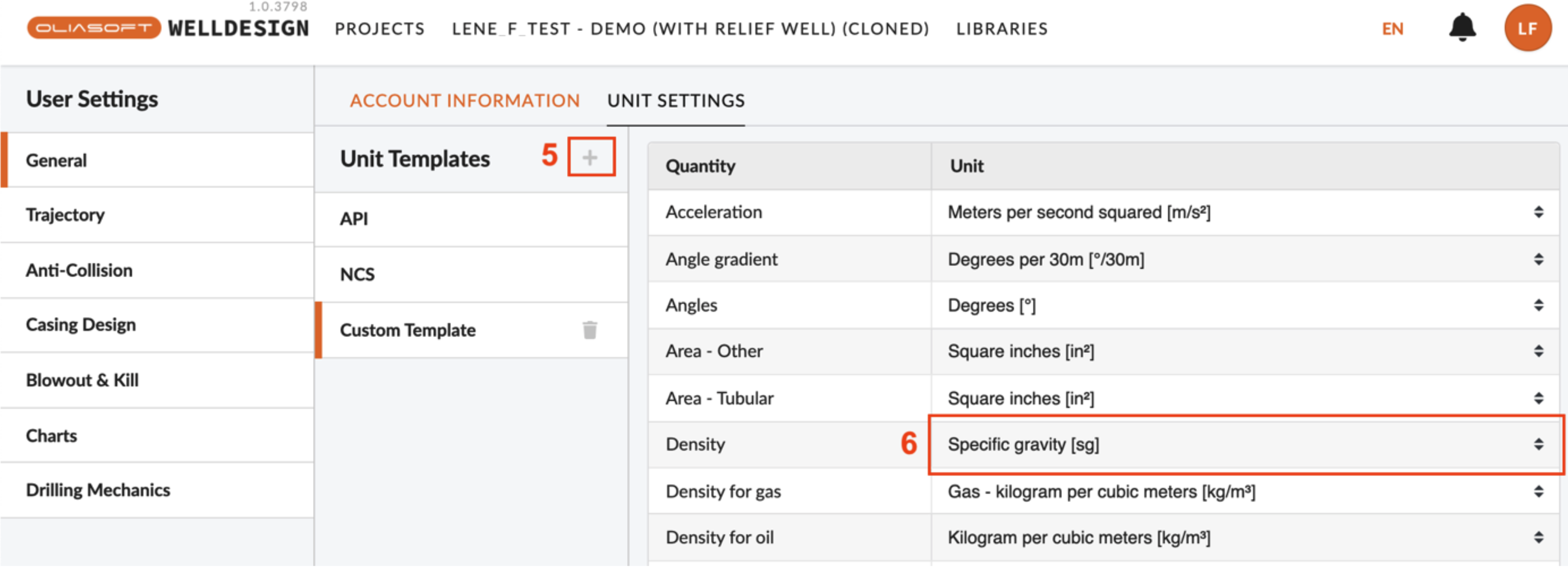
“API” and “NCS” are standard unit templates which cannot be deleted or edited by users, but custom unit templates can be created by clicking the plus button, marked with a 5 in the figure. A pop-up window will appear, where a name for the unit template is to be defined.
Select the unit template by clicking on its name in the list.
The unit to be applied for a quantity is defined in the table on the right-hand side. Click on the current unit used for the quantity, as shown for density with a 6 in the figure, and select a new unit from the drop-down list.
How to apply unit template to datasets:
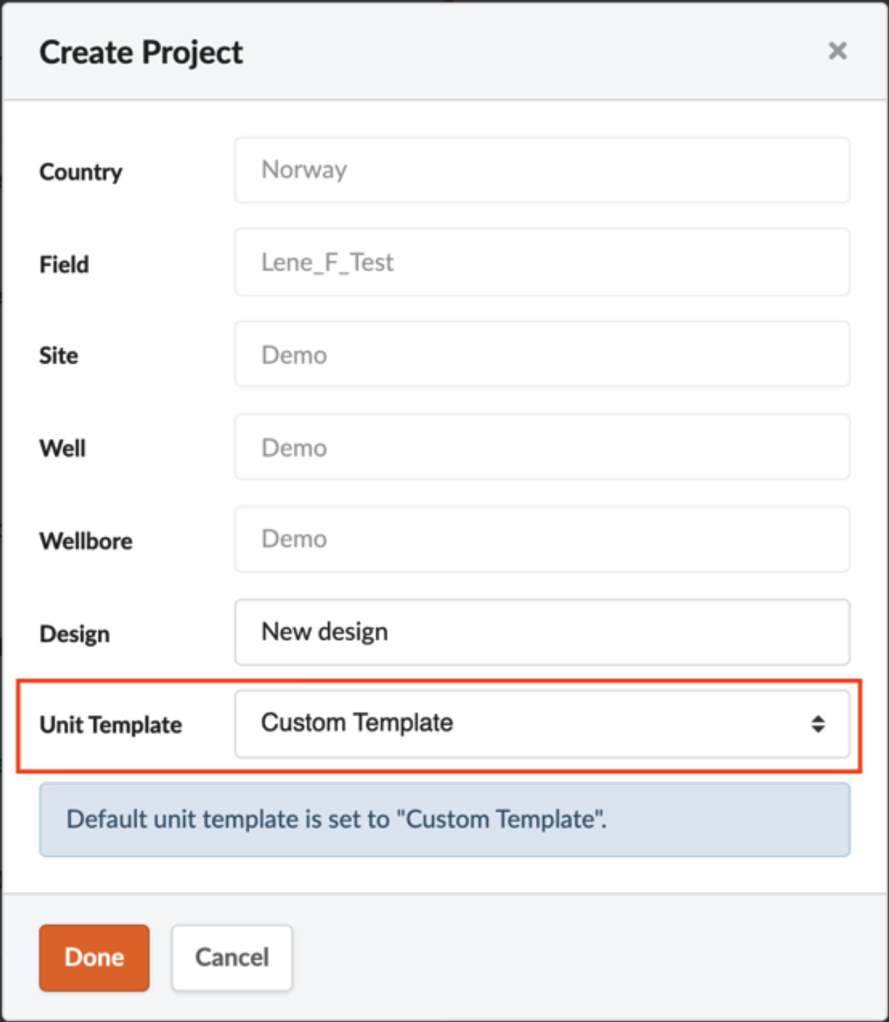
When creating a new project, the unit template is selected in the field marked in the figure below:
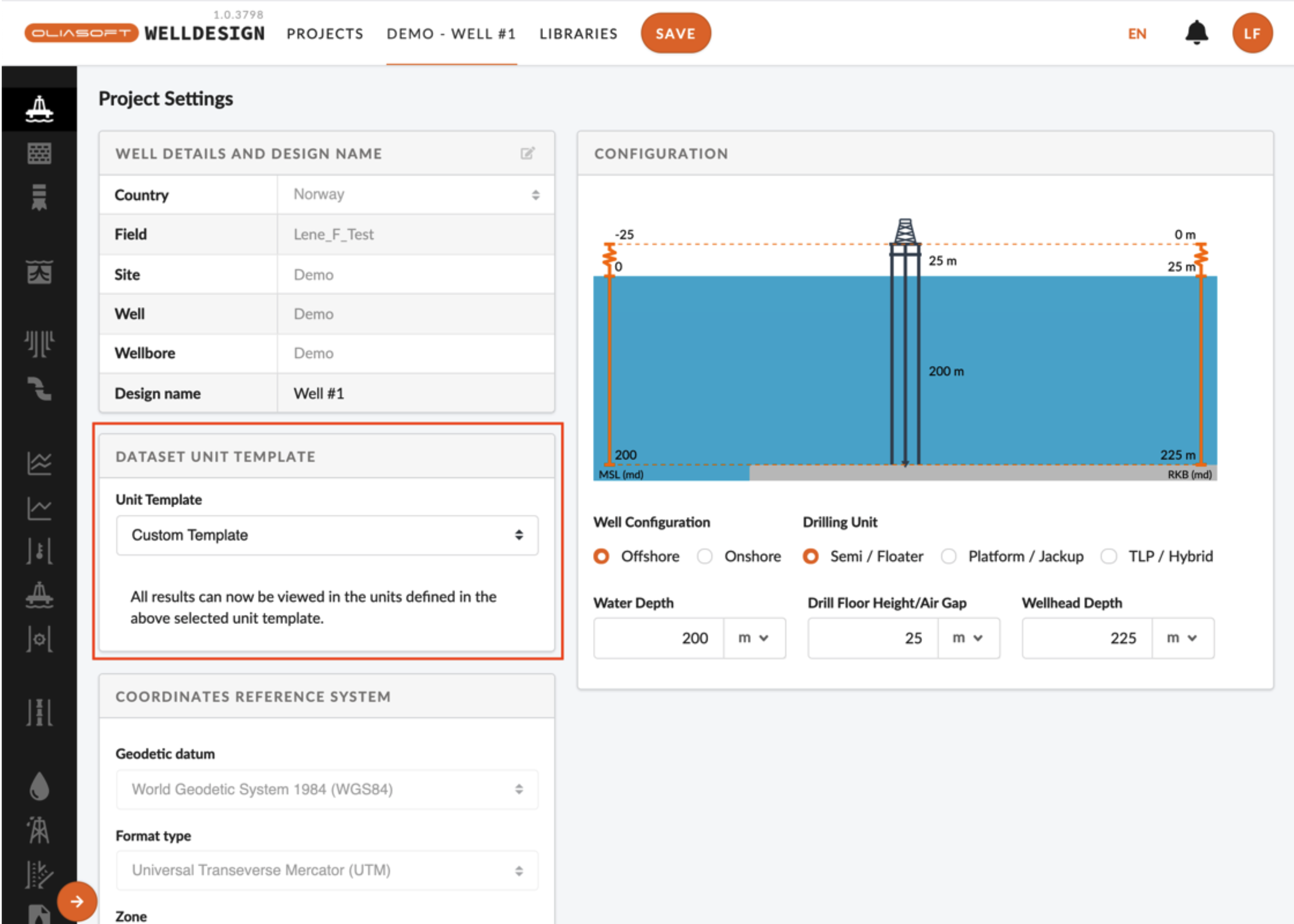
When a project has already been created, the applied unit template can be changed in the “Project Settings” section, as seen in the figure below:
Depth Reference
1. The ability to use TVDSS and TVDRT as a means to change depth-oriented calculations.
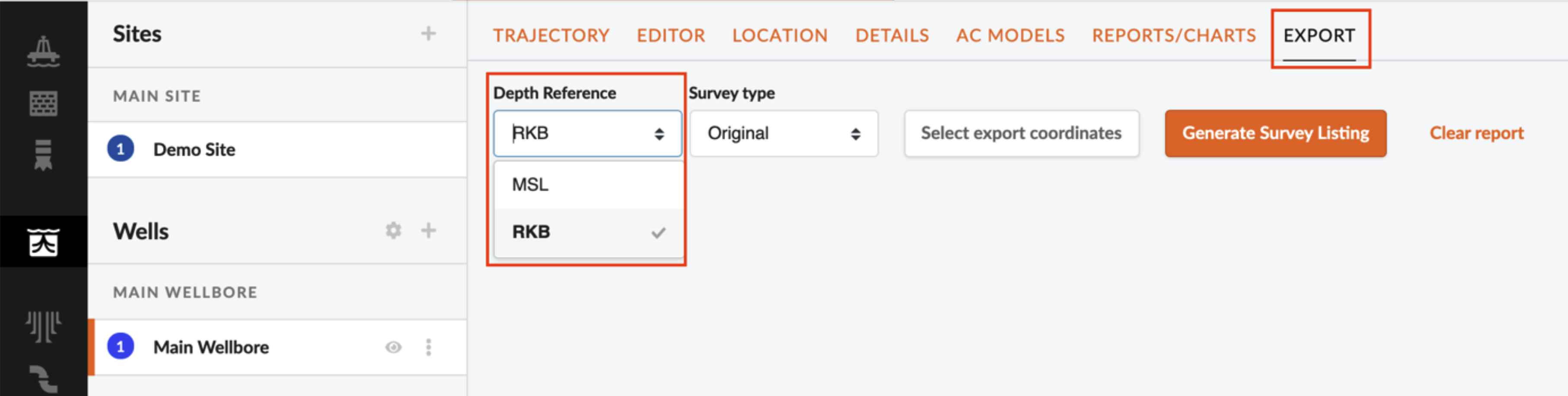
Currently, the user can only specify whether MSL or RKB has been used when exporting survey reports.
2. In Oliasoft the depth reference is defined once only at the beginning of the project/design. At the design phase of a well, we do not usually have data about the rig/platform to be used for drilling, so we intend to reference to the ground level. Later, when we identify the rig KB, can we just go back and change the depth reference to KB and we have everything updated or do we need to create a new design with a new depth reference?
Depth references is handled in the following way at the moment:
- You can define a depth reference to the “site”. All information you put into the project will be relative to this reference.
- If you decide to import other wells for the purpose of doing anti-collision, we adjust the depth reference in all wells so that they have the same reference.
- Exports of trajectory can be exported both as RKB and MSL reference.
We do NOT currently have the option to automatically adjust all depth inputs based on a change in RKB reference. This will probably be out later this year.
3. Does Oliasoft have the capability to different data to one depth reference? Or do we need to do some data preparation outside of Oliasoft I have got survey data from Ground Level, Formation Data (Fracture pressure, pore pressure from Rotary table)
Most inputs must be prepared to be in RKB reference at the moment, except for trajectories where we have an option to import straight MSL or ground level references. So for the survey data, it should be possible to put those in without adjustments.
Formation data should be from rotary table.
4. Formation inputs should specify TVD is RT or SS for clarity.
If otherwise is not specified, RKB is used as the reference datum in the application. Letting the user switch between MSL and RKB is in our pipeline.
Drill String/BHA
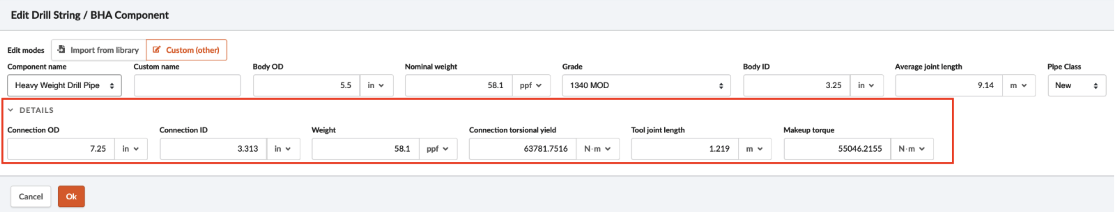
1. Connection OD is not an entry value for custom defined connections. (Unsure how this impacts e.g. buckling numbers.)
Connection dimensions for a custom component can be edited by opening the Details section in the modal.
2. With no service company tools in the library, generating a representative drilling BHA is time consuming.
It would be very much appreciated if information about service company tools is distributed to us, we can then examine if they can be implemented in the Oliasoft part of the libraries.
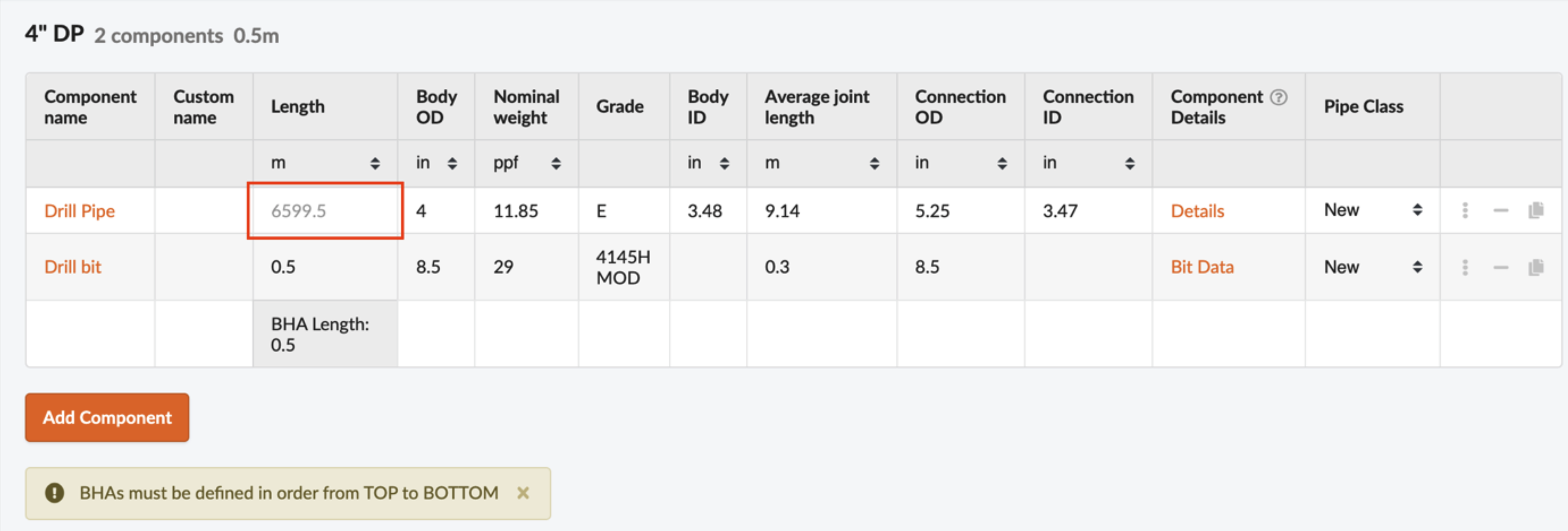
3. Drill string tab – auto-added DP to final TD, even if its BHA or casing string for shallower section, adds confusion.
In the drill string components table, the length of the first component cannot be altered as it is meant to represent a variable length of drill pipe, whose length is adjusted to fit the sections and operations applied in the simulations.
The variable length is for visual purposes and is the length to TD minus the BHA length.
4. Cannot visualize the BHA as you make up the BHA This functionality is in our pipeline.
Trajectory Design
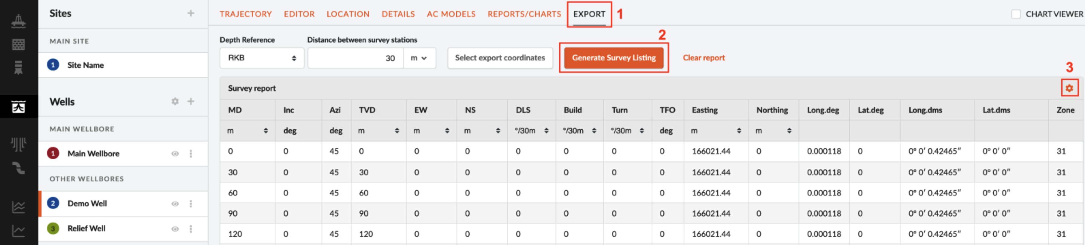
1. Not clear how to establish actual survey data and establish actual error models.
How to generate a survey listing of a trajectory in Oliasoft WellDesign™:
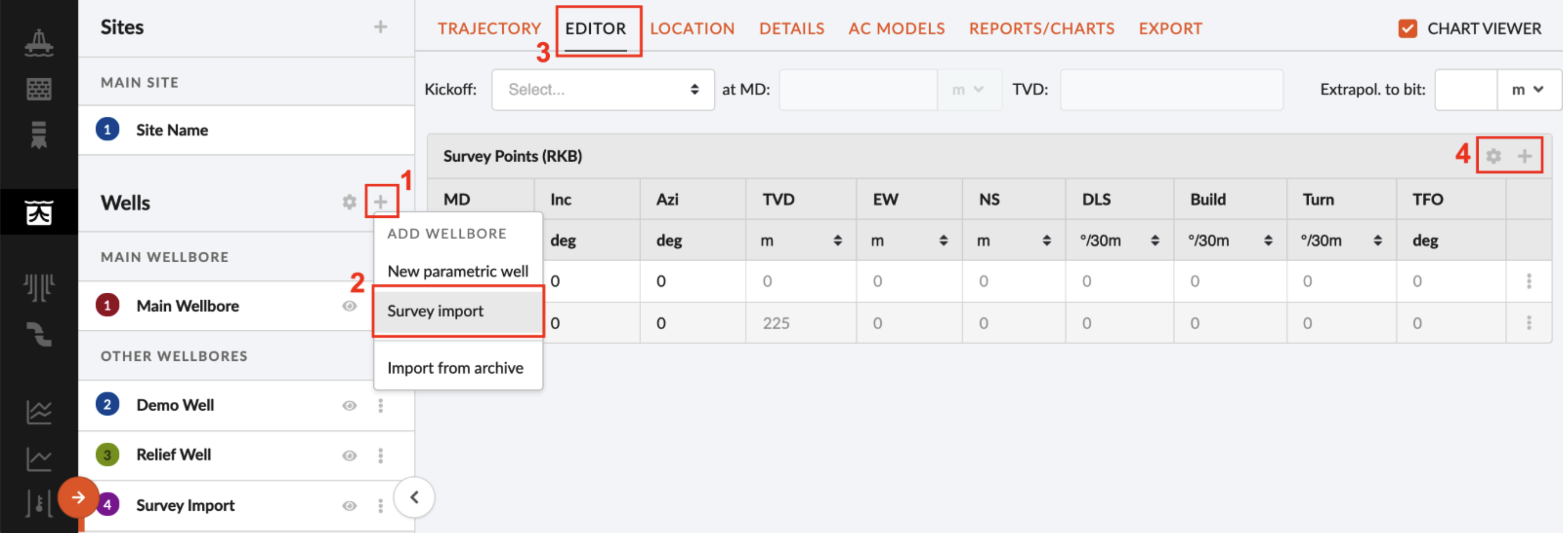
How to create a survey well in Oliasoft WellDesign, which allows you to either input survey data manually or upload file/paste data from clipboard:
How to define error models and apply them to the trajectory:
2. How to define intrinsic anti-collision model
We have full anti-collision model support where you can either use our anti-collision models or add your own as IPM files, but we do not have the (more experimental?) intrinsic method.
3. The ability to start a well as a sidetrack. Tying into the original mother bore survey. (Did not get this feature)
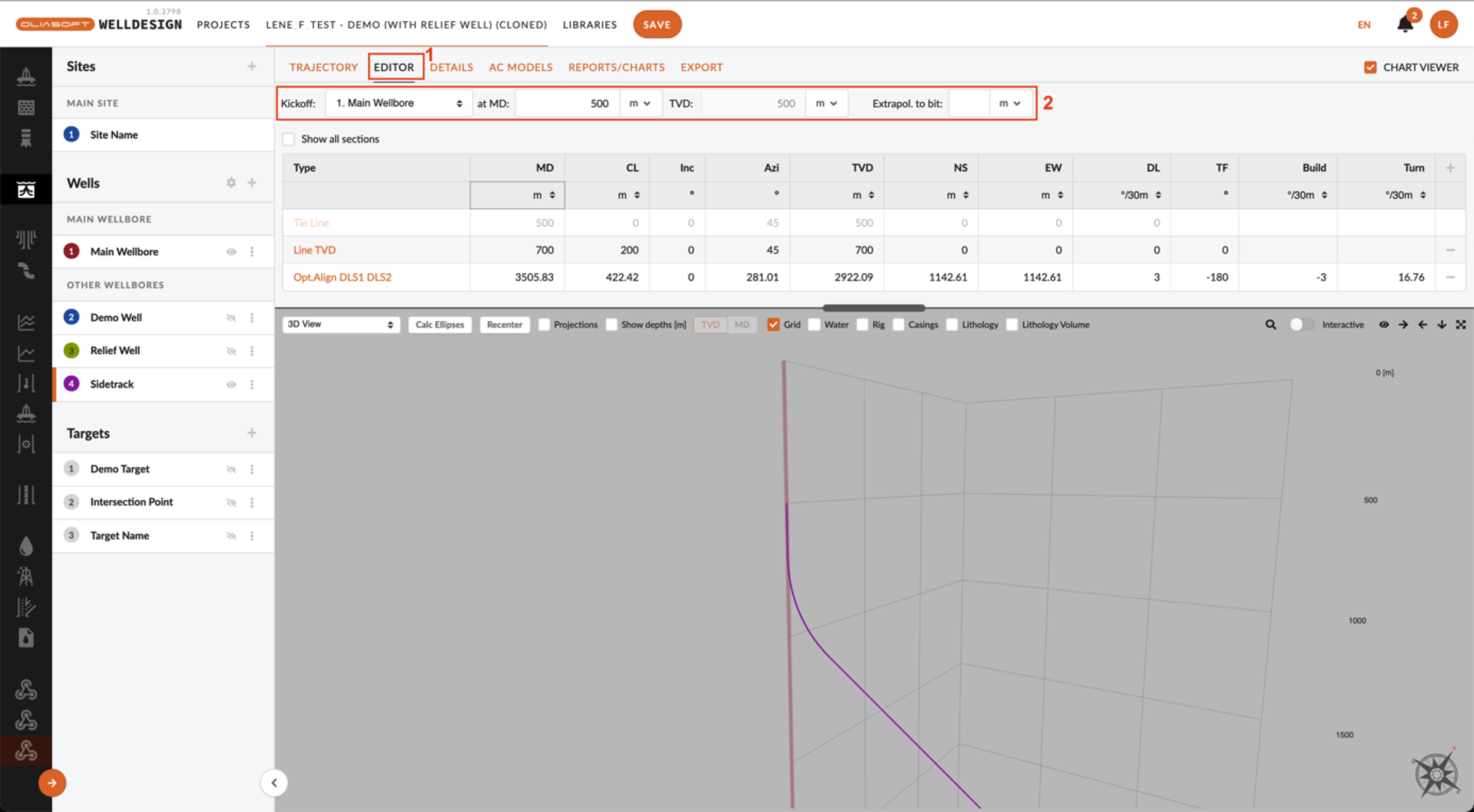
A well can be defined as a sidetrack/kickoff in the “Editor” tab. In the area marked with a two, the mother well and the depth at which the sidetrack is to start can be defined.
Well Setup
1. Tapered completion It took me some time to figure out how to fix this. I have got 13-3/8’’ x 9-5/8’’ Liner configuration and the desired completion is 10-3/4’’ vs 7-5/8’’. When add the 10-3/4’’, I see a red highlight over the cell with a warning error that it’s larger than the 9-5/8’’ (depth to bottom of 10-3/4’’ is defined above top of liner). However, the calculations are run without error
- I would like to check if the final results are not affected with this red highlight in place?
- The initial Pickup/Slack off weight with the packer, is it defined at the packer section or at the string initial conditions tab?
Noted. If you send me a link to the project, I will check for that red validation flag. It is supposed to take depths into account so that if the 10 ¾" is set above the 9 5/8” you should not see it. There has been some recent updates to this, so perhaps it is good now?
Pickup / Slackoff weight for the packers can be found in the packer tab. Each packer has some settings where you can define pickup / slackoff for each packer. The options under initial conditions are applied first.
2. I define the packer pickup weight ( 10t, 20t, and 100t), but I do not see the effect on loads. Could you please guide us through the procedure and the loads where the effect of the initial conditions can be seen? For the casing with TOC, the effect of the string initial conditions are seen clearly
The pickup / slackoff weights on the packers are actually applied right after what we call “initial conditions”. So you would not see those on initial conditions, but rather in axial loads for a load case. If you would make a load case with 0 differential pressure and compare initial conditions with axial load of that load you would see that it has been applied to the load case.
I understand that this may seem un-intuitive so we will make an option in the user settings to apply this before or after what we call initial conditions. The reason it has been implemented like this right now is due to feedback from wellcat users and what they are used to seeing.
3. Kick Tolerance was not a module included in the trial package.
Kick tolerance is automatically calculated for each section.
4. Only possible to have one open hole section in each design, so kick tolerance per section required a cloned design.
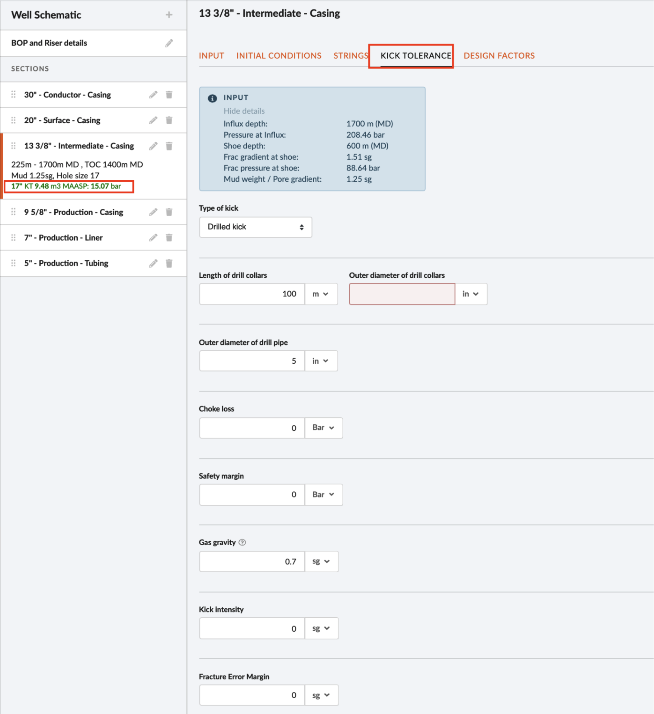
The kick tolerance is now shown for all casing sections, except the conductor. As seen in the figure below, the calculated kick tolerance is displayed when the section is selected and thus, it is not necessary to have multiple open hole sections to get the calculated kick tolerance.

5. Could not find a way to insert a casing in between a casing once the casing scheme is outlined.
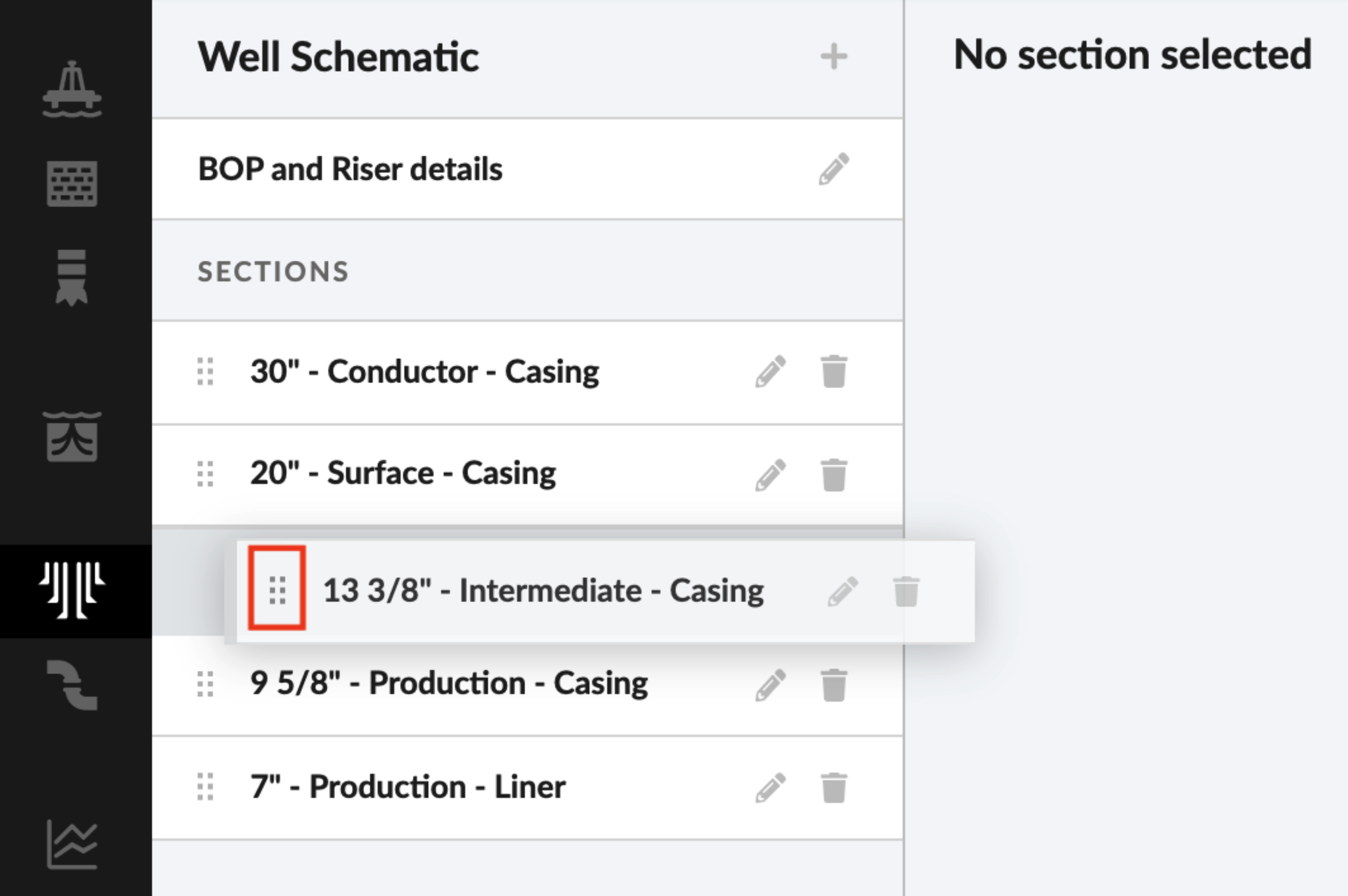
Casing sections can be moved to a different position in the list by using drag and drop. By clicking the area marked in the figure below, the section can be moved to a new position.
Casing/Tubing Design
1. Is there a way to save a casing loads template, i.e. to specify a selection of load cases for surface, intermediate and production strings that I can quickly apply?
We have functionality for automatic casing design. That means you can define a rule set which consist of rules for setting depth, mud strategy, load cases and string priority. Here you will find a short description on how to define and use these rule sets. The video will be relevant for you from approx 38 seconds into the video. https://vimeo.com/560361037 .
2. Custom load cases cannot be copied from Project to Project.
We do not have this functionality yet.
3. Cumbersome to create completion load cases. Issues with picking up pressure and temperature profiles.
In the near future it will be possible to automatically generate a tubing load case from the temperature simulation, but for now the appropriate profiles must be selected manually by the user inside the casing load. The issues have also been solved.
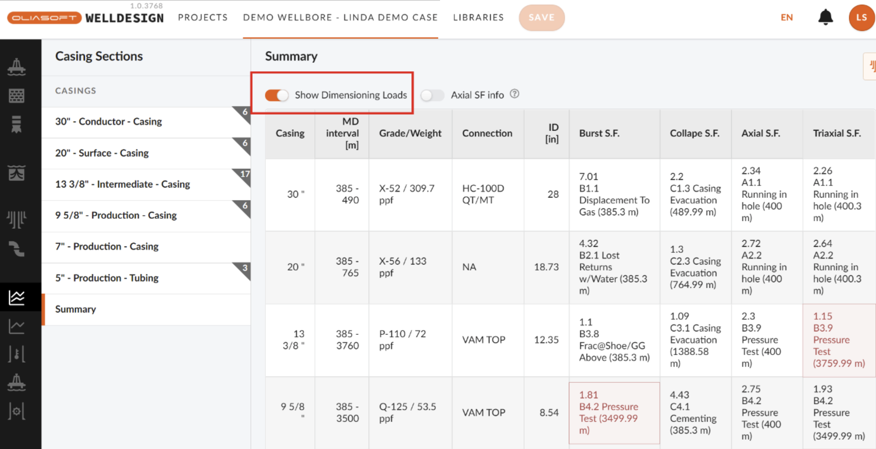
4. In casing design – when a design factor is less than necessary the summary table turns red (so far so good). It doesn’t tell me which load case is causing that - is it only possible through looking into all individual load cases to find the problem?
If you toggle on the 'Show dimensioning loads' it will also give you which load case is causing the load to be below the design factor.
5. Limited amount of pre-defined load cases. We currently offer 8 predefined tubing load cases:
Burst:
- Displacement to gas
- Pressure test
Collapse:
- Casing evacuation
- Negative pressure test
Installation load:
- Overpull
- Pre-cement static load
- Running in hole
Do not hesitate to send a request if other predefined tubing loads are desirable.
6. Casing Wear prediction was not a module in the trial package.
Casing wear will become available as a part of the Drilling mechanics module, most likely as a plug-in using Drillscan’s model.
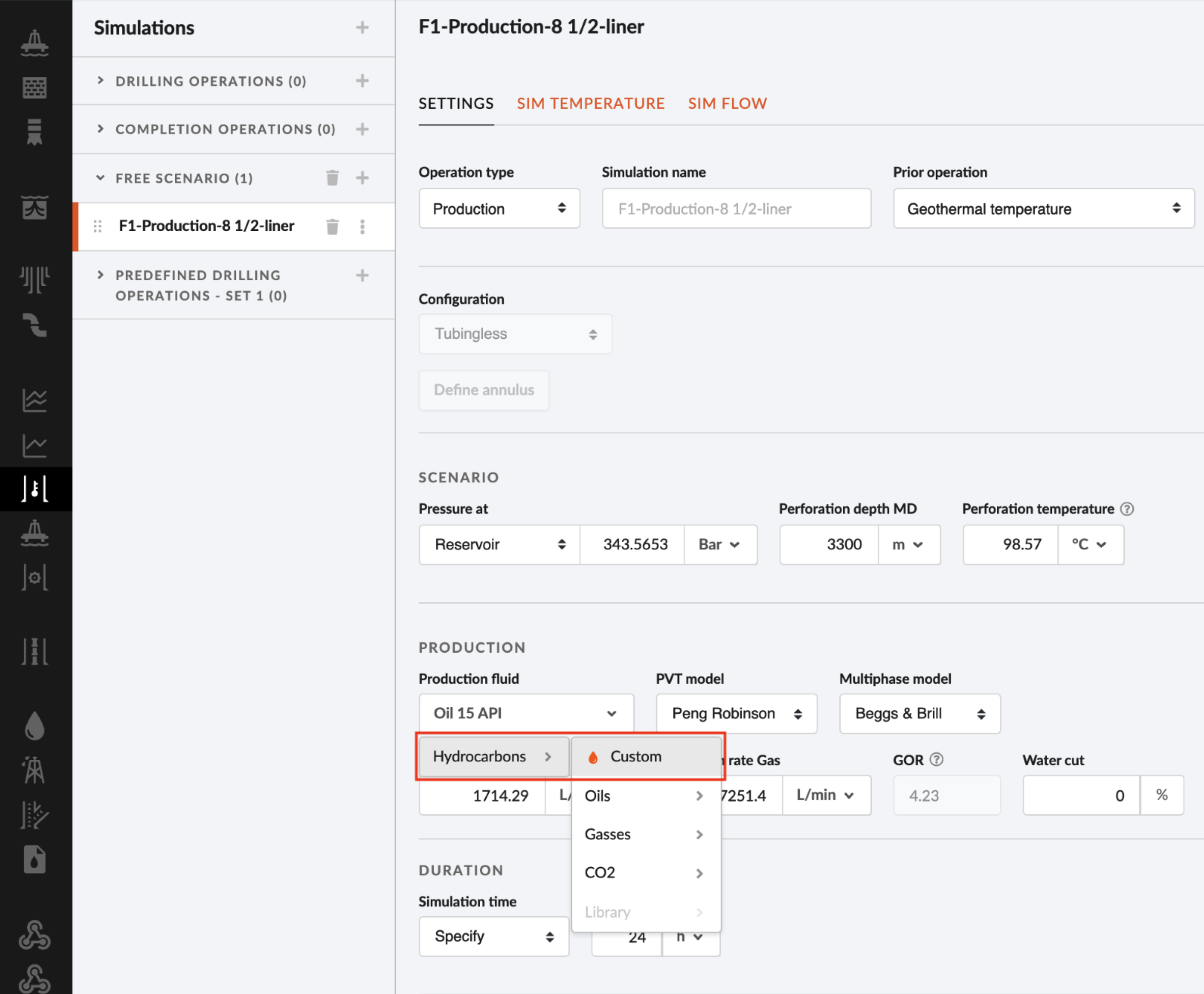
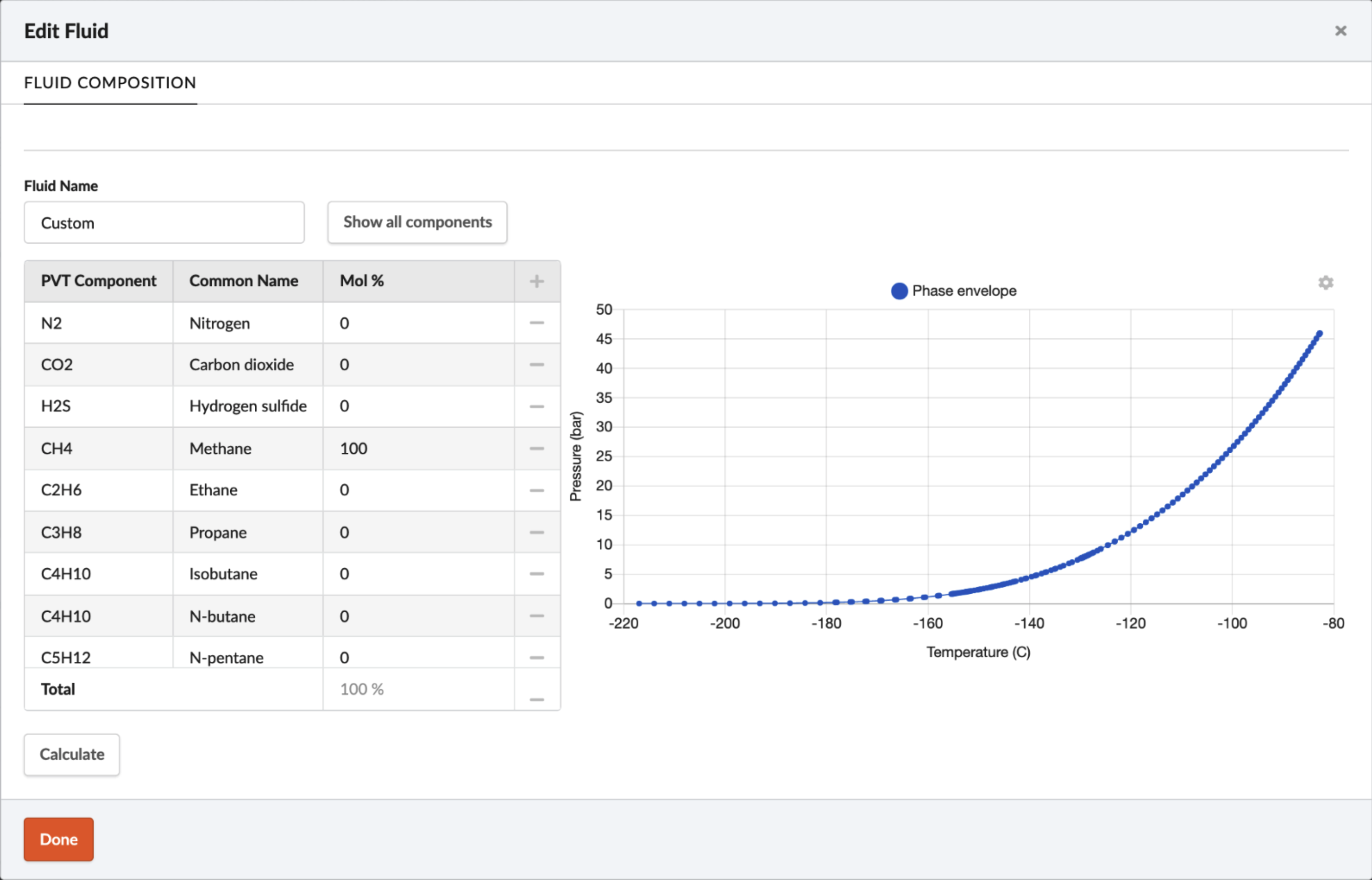
7. Customized items are not available in the drop down for temperature simulations. (This has been reported to Oliasoft and a fix is allegedly in progress.)
We are working on having a link to the hydrocarbon library for temperature simulations, it is currently seen as the disabled “library” option below. In the meantime, it is possible to define custom hydrocarbon fluids.
8. Could you please show how to perform annulus pressure build up simulation? And automated design?
Please find video support for both annulus pressure build up and automatic design.
https://docs.oliasoft.com/user-guides-1/video-user-guides/afe-simulation
https://docs.oliasoft.com/user-guides-1/video-user-guides/automatic-design
Drilling Mechanics
1. Not possible to load actual data and use it to calibrate models in Oliasoft.
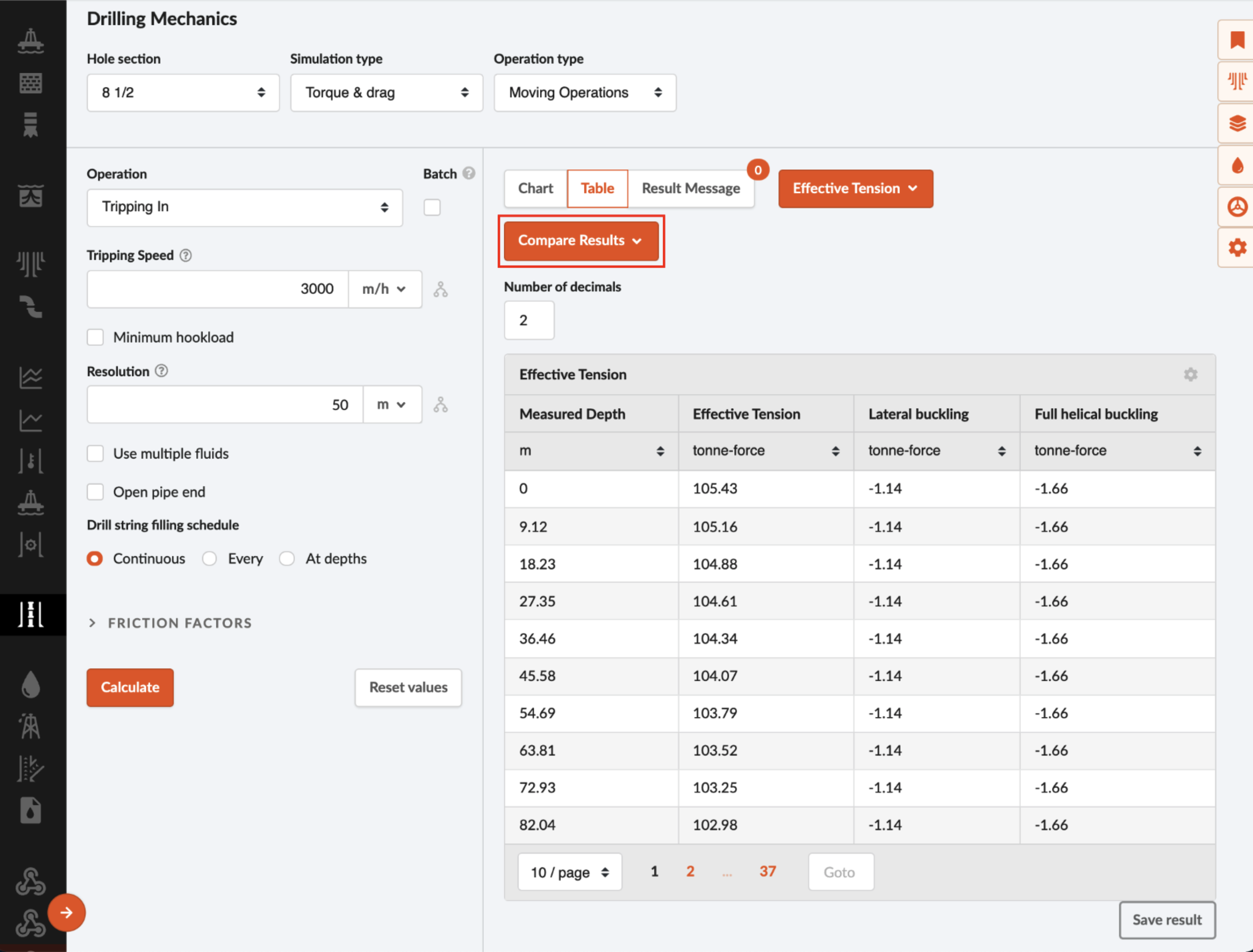
It is possible to load ie. Real time data into a result chart to show together the simulated results from Oliasoft WellDesign™.
2. Drag and Torque simulation The stuck point is always at the bottom of the string? How can we simulate for a tubing with packer in the mid but not at the bottom of the string? The overpull value depth, it seems to me is the bottom depth? If I would like the value to be a surface - hook value is that possible to simulate?
As you have observed, the overpull value is calculated as if the stuck point is always at the bottom of the string and then it iterates over the string to find the the maximum over pull value (surface - hook) based on the weakest point in the string. At the moment we do not offer the functionality to specify a depth where the string is stuck. This would however not be a big thing for us to add. In your example this might work as letting a user specify a depth where the string is stuck (packer depth) and then only iterate over the string above this point.
3. Cannot simulate on mud pumps with specific liner size which determines the pumping capacity per stroke.
We do not have this functionality.
4. Does not help you place equipment limitation lines
We do not have this functionality in place.
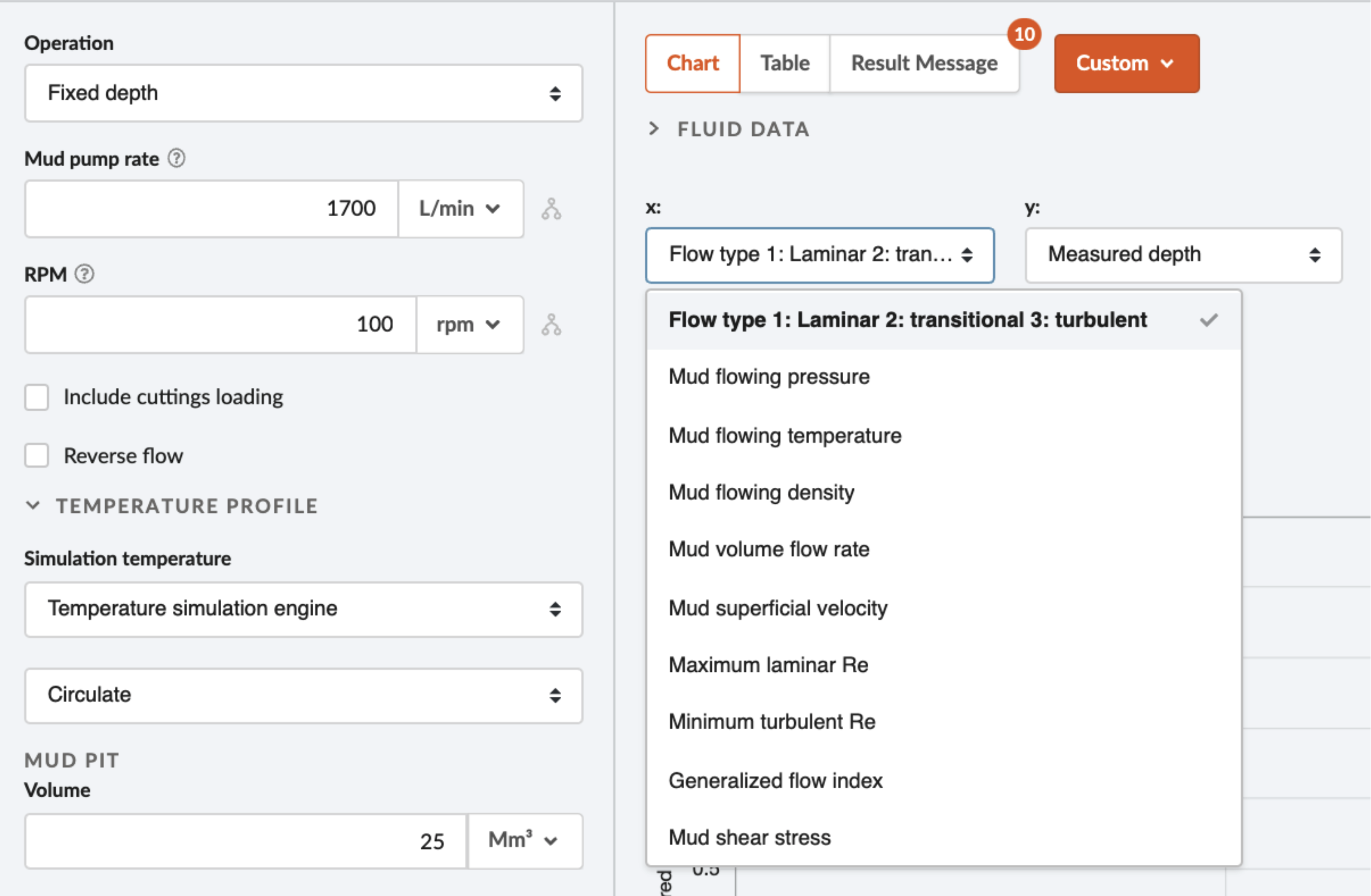
5. Does not help you determine if you are in a turbulent flow etc which can aid hole cleaning.
If you run the Fixed Depth mode in Hydraulics and plot the “Flow type: 1 Laminar 2: transitional 3: turbulent” option vs MD in the custom chart you will get a chart showing you the various flow regimes in the entire well. To have the option of plotting the flow types, diagnostic data has to be enabled in the simulation settings.
6. Does not specify the min flow rate for hole cleaning at set ROP, also a slide bar for ROP is useful to see how the flow rate requirement changes.
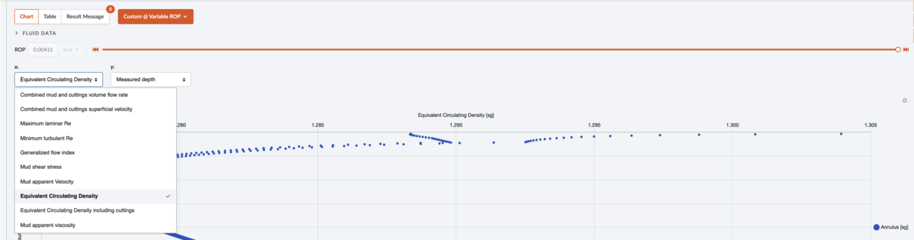
If you run the Variable ROP operation type in hydraulics and select the Custom @ Variable ROP you will be able to make a custom plot and have a slider that covers the ROP interval you set prior to running the simulation. You can then eg. Plot the “Combined mud and cuttings volume flow rate”.
Blowout & Kill
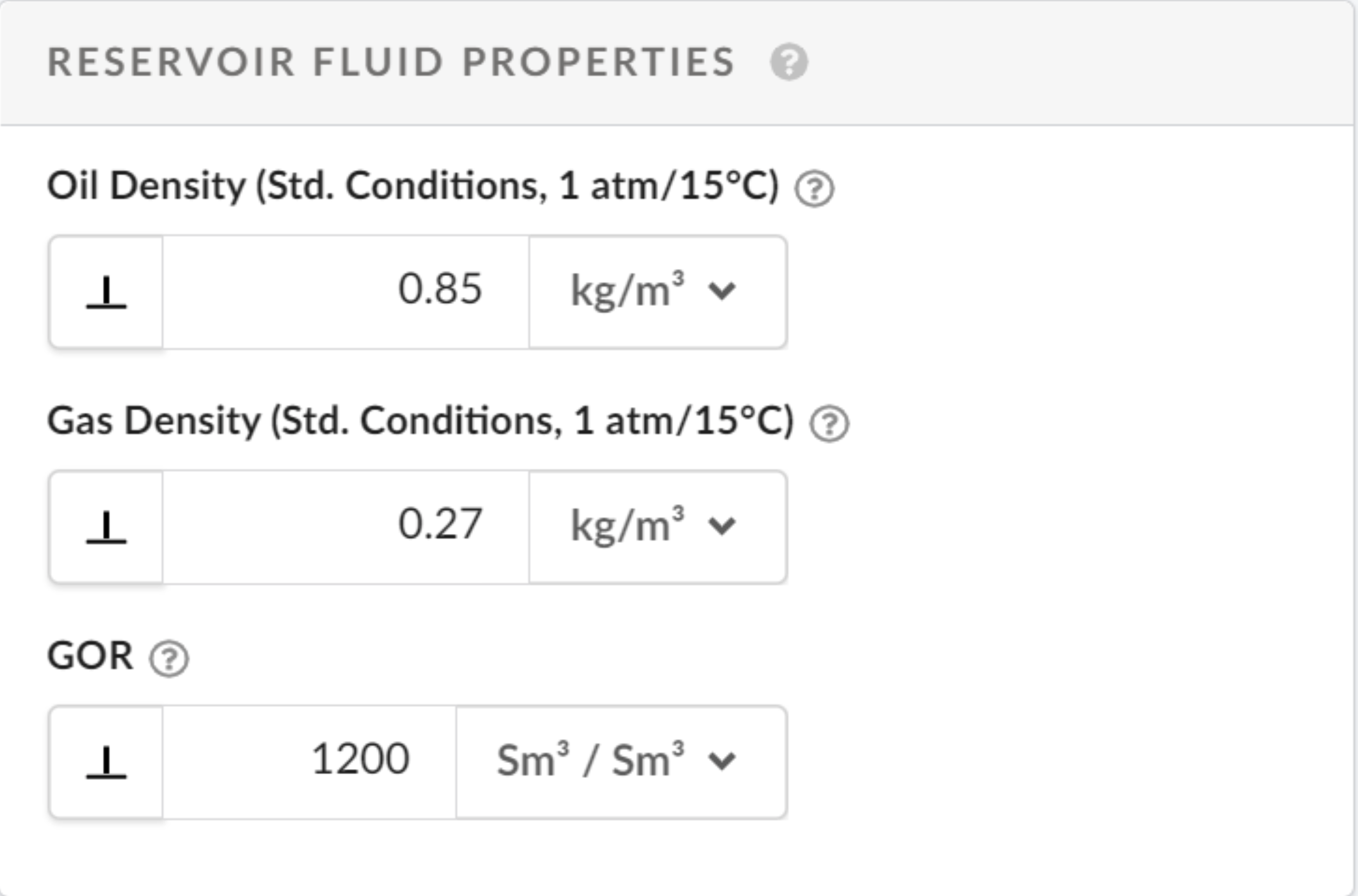
1. Is the blowout module active in my trial license? I can enter data and run simulations, but no matter what I do the discharge rate remains zero everywhere.
The trial license includes all functionality, including blowout and kill. The 0 rate may be due to your fluid density (in the reservoir section). I think the oil density should be 0.85 sg, not kg/m3. Please let me know if this was a correct input from your side.
Reports
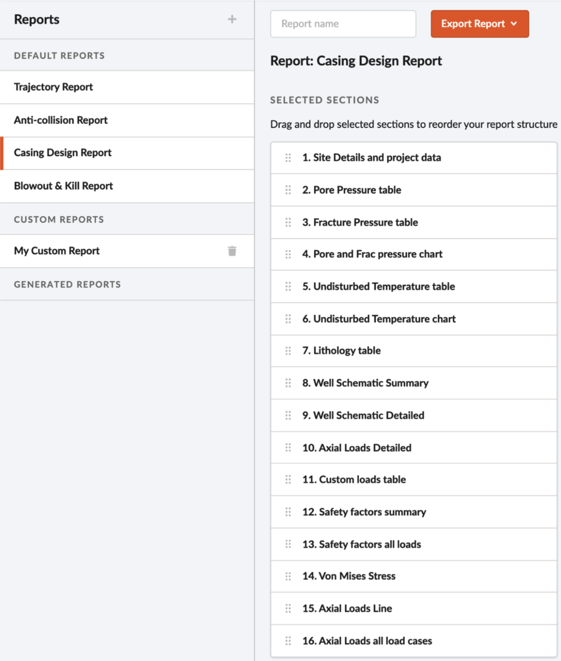
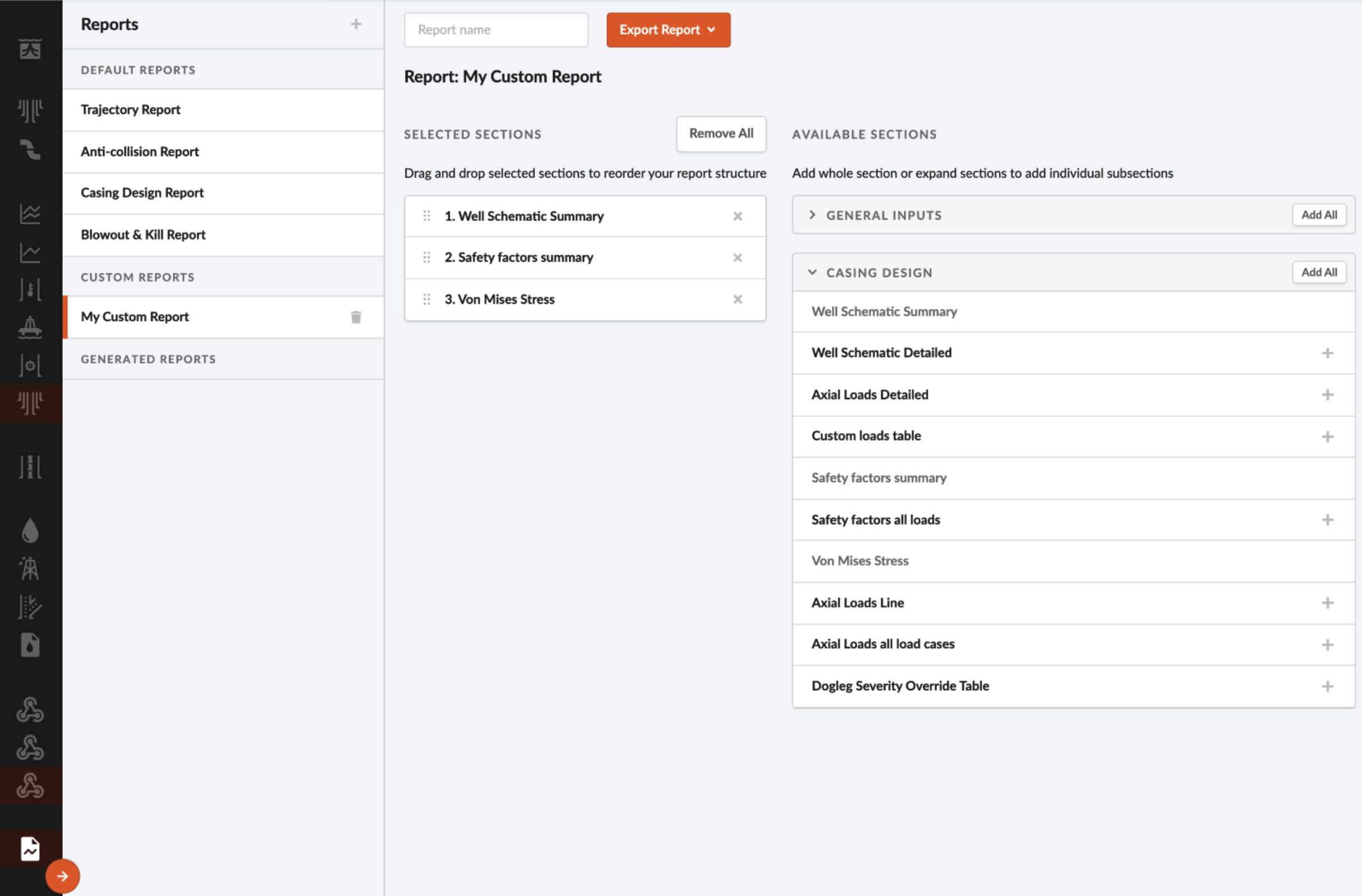
1. Rudimentary with what’s available, e.g. printing out input & output report not available in Casing Design
The reports modal is still under development, but it allows the user to download default reports and custom reports. Please elaborate if there are some specific inputs or outputs you would need in the report.
2. Trajectory planning fixed one-page reports.
Are you referring to the one-pager report generated by compass? The report module is still work in progress and at the moment we do not have this functionality.
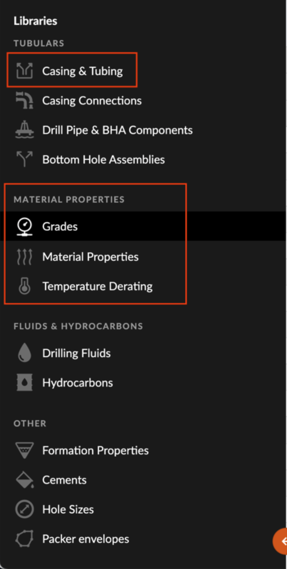
Libraries
1. Addition of non-custom equipment is not easy in the library. (Addition of pipe and casing should be easy).
In our User Guide, an example is given on how to add a casing/tubing to the library. Custom grades, temperature derating and materials can also be defined in the library, these can then be selected from drop-down lists when creating a casing or grade, respectively.
Please provide more feedback on what you found difficult in regard to defining components in the library, if you did not find the above information helpful.